How to build a 17DOF biped robot controlled by the raspberry pi.
PARTS:
RPI Zero W (Barebones Kit) – https://goo.gl/fSioxP
4 Amp Power Adapter – https://goo.gl/js4Uc7
16GB Micro SD – https://goo.gl/FDqZal
120 pcs jumper cable – https://goo.gl/spWoaC
Biped Kit (If link broken check aliexpress.com) – https://goo.gl/He5XPp
Maestro Servo Controller – https://www.pololu.com/product/1354
Linear Bench Power Supply (for testing purposes, better than the one I used) – https://goo.gl/6YYKGf
Misc. items:
-Cable Labels
-Rustoleum Spray Paint (Etcher Primer x2 and Color of your choice x2)
-liquid electrical tape
-mini usb cable
-3m double-sided tape
-hot glue gun
-small philips screwdriver
-multimeter
-soldering supplies
-zip ties
3D Printed Parts:

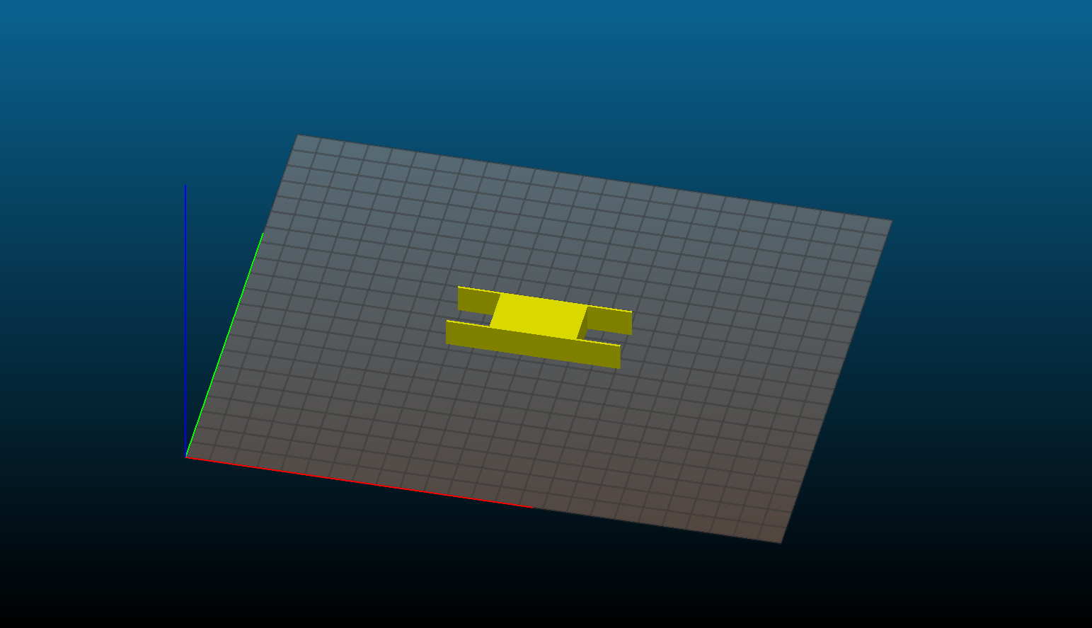
“work in progress”
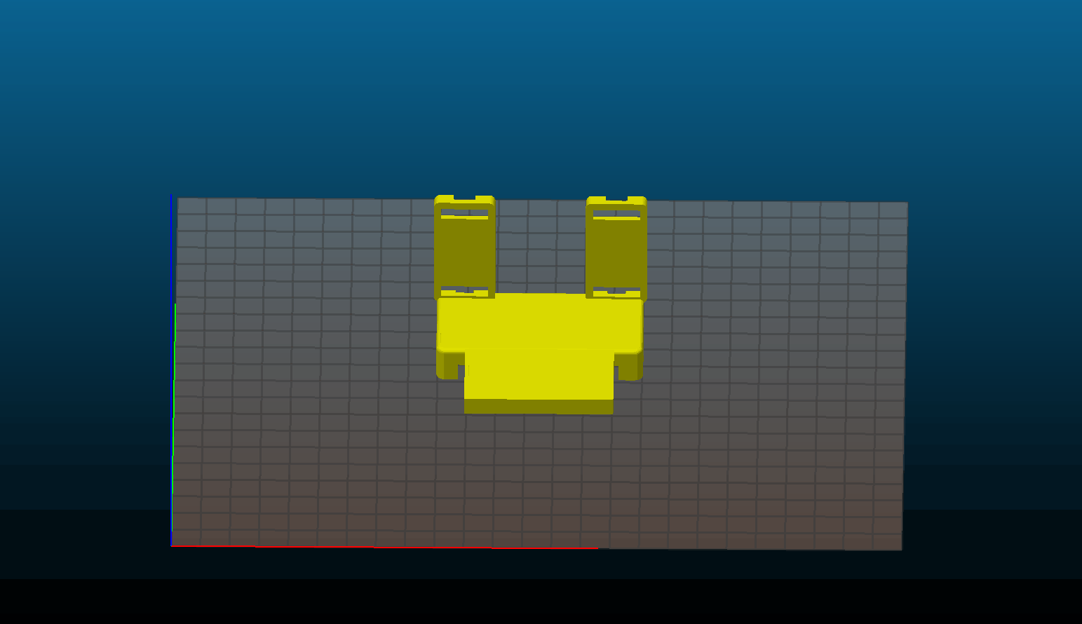
STL files
Denji_3D_Parts
PHYSICAL ASSEMBLY:
Note: Assembly based on personal experience as no instructions were provided
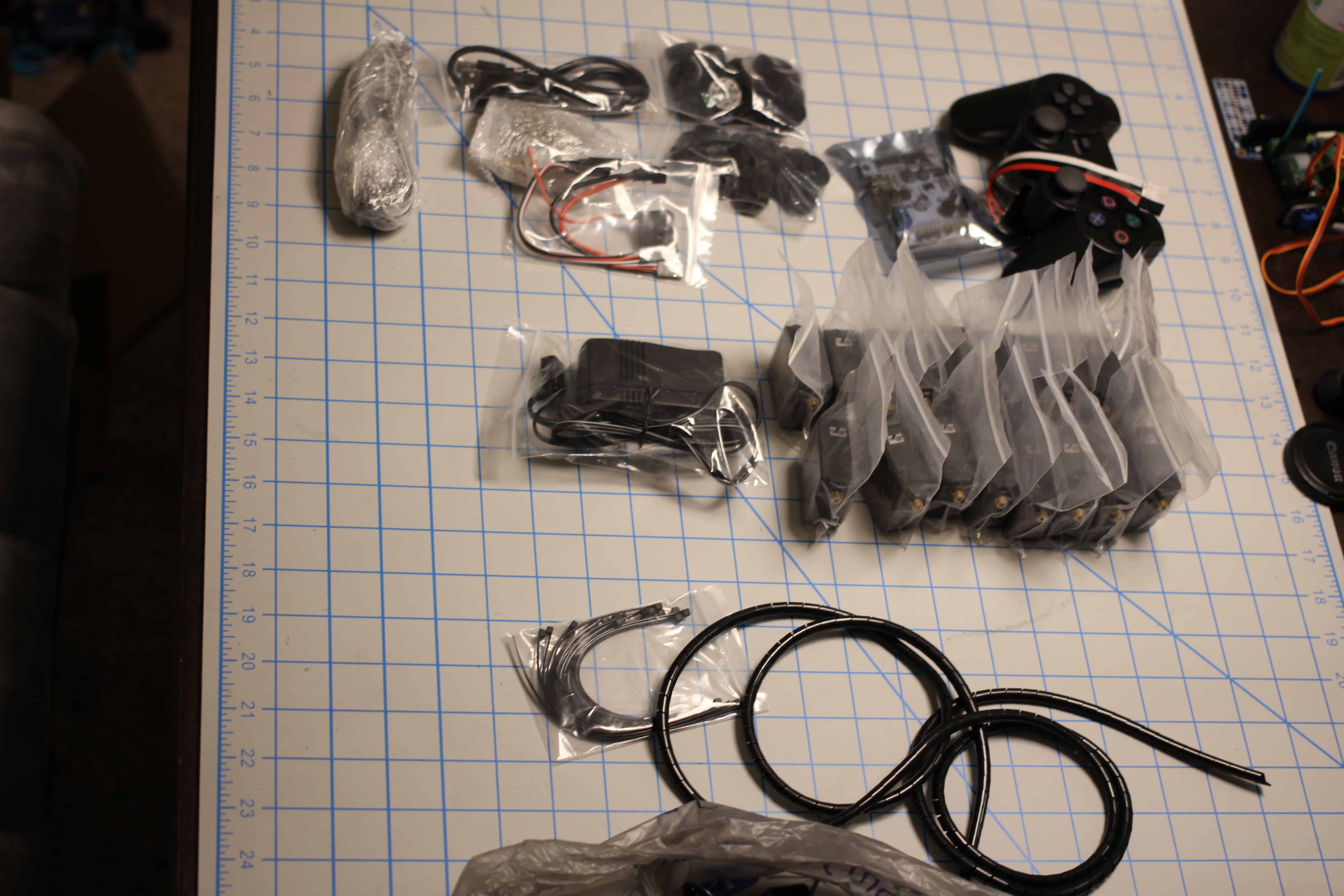
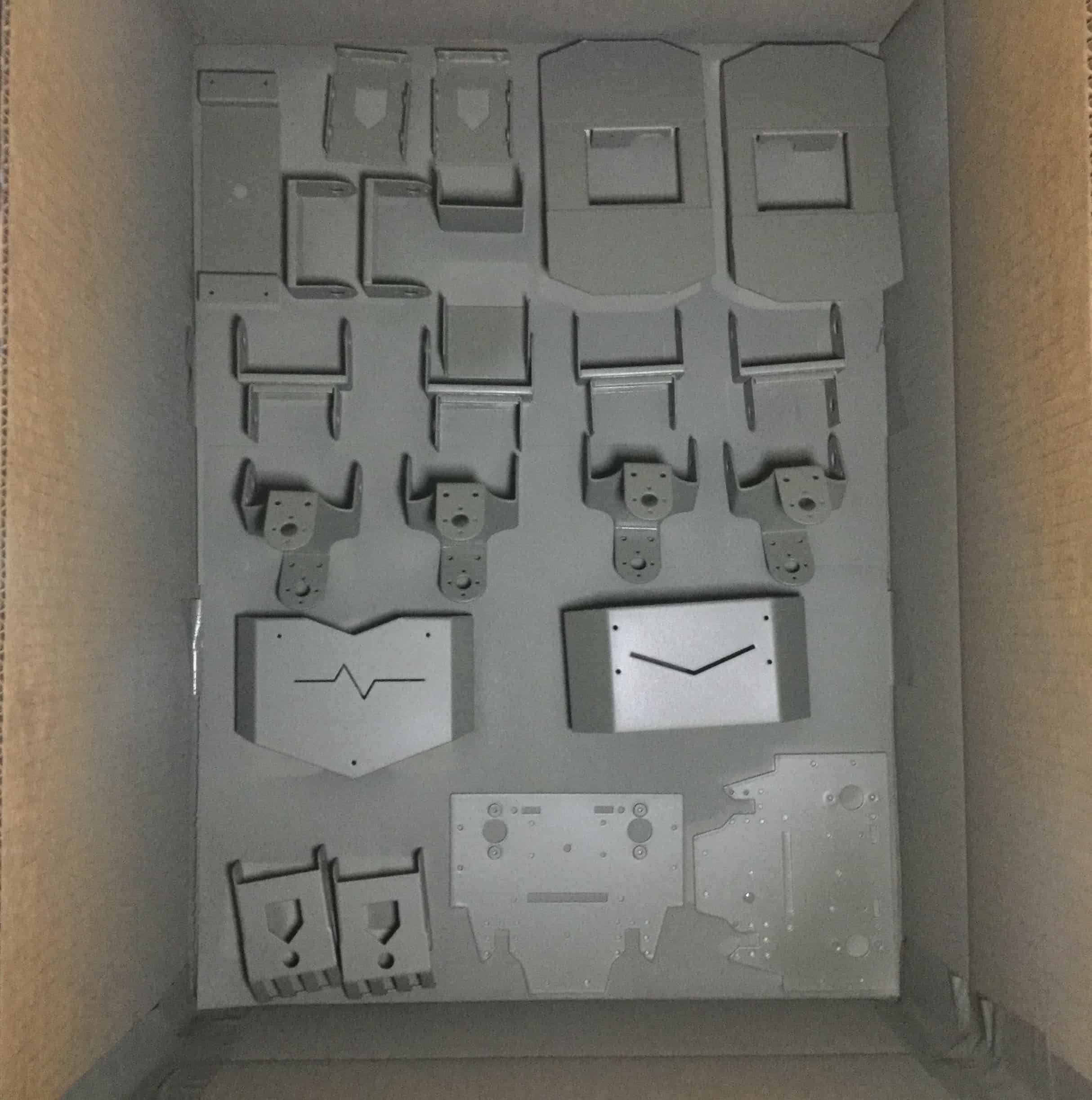
1. Unpacking kit.
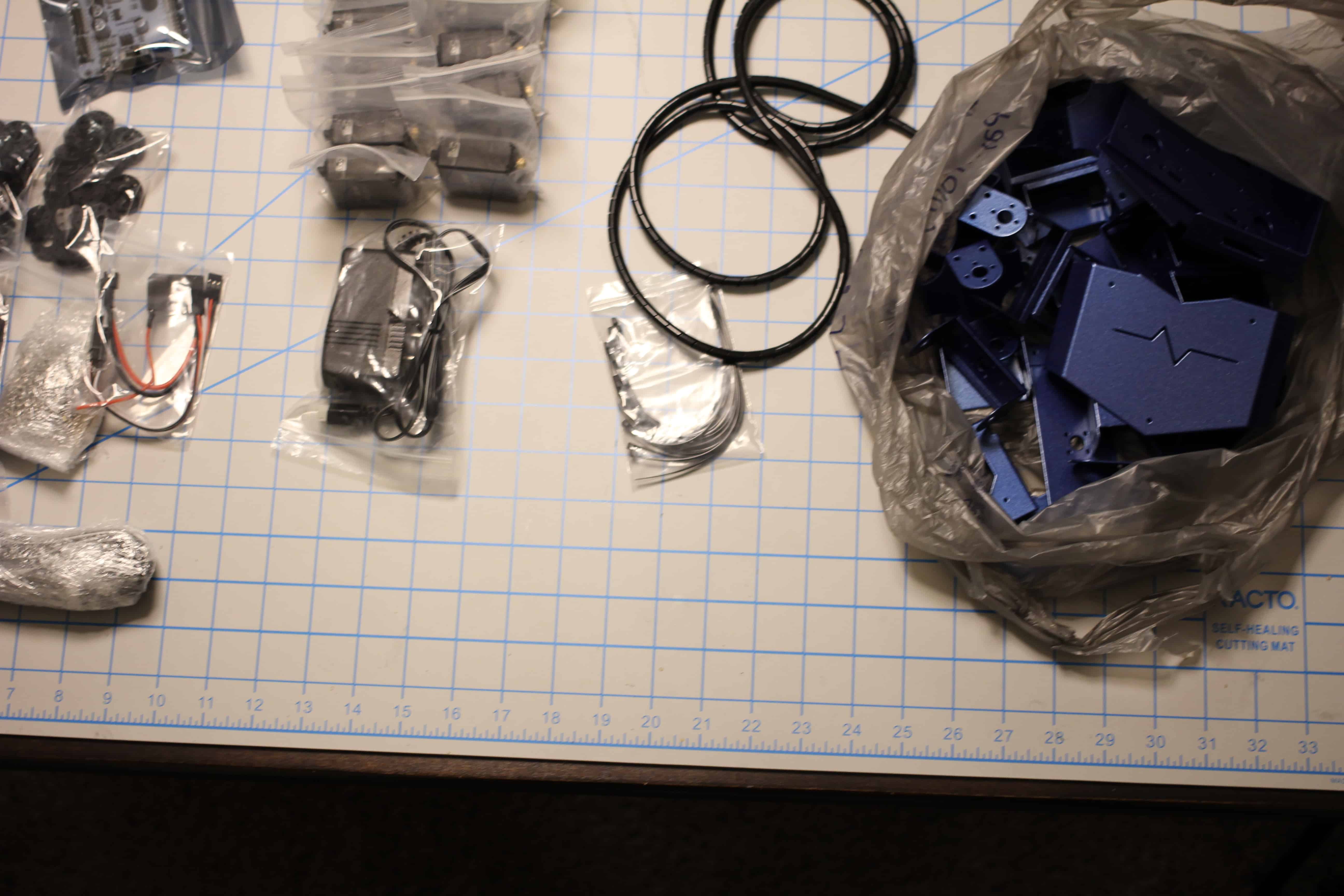
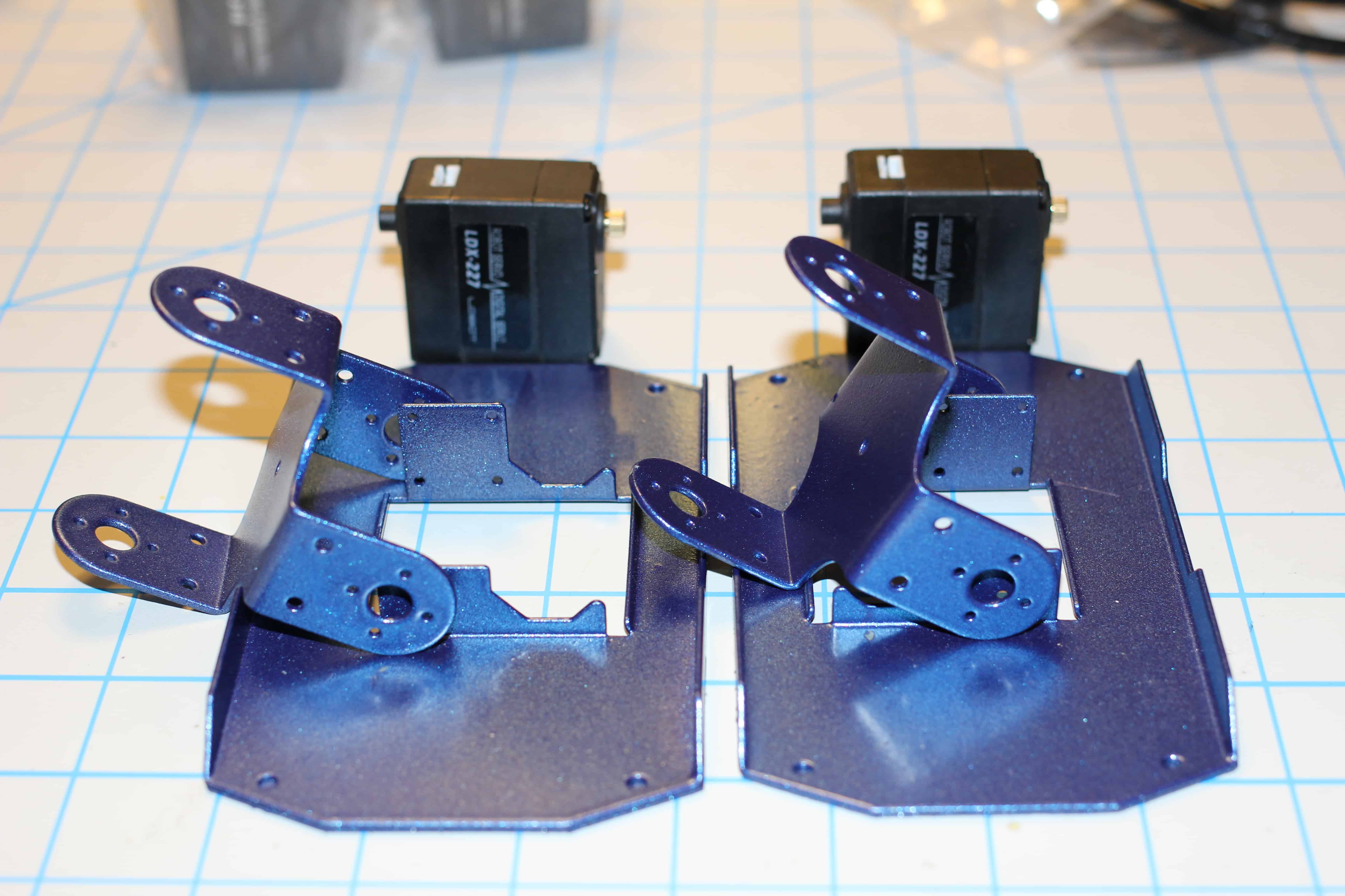
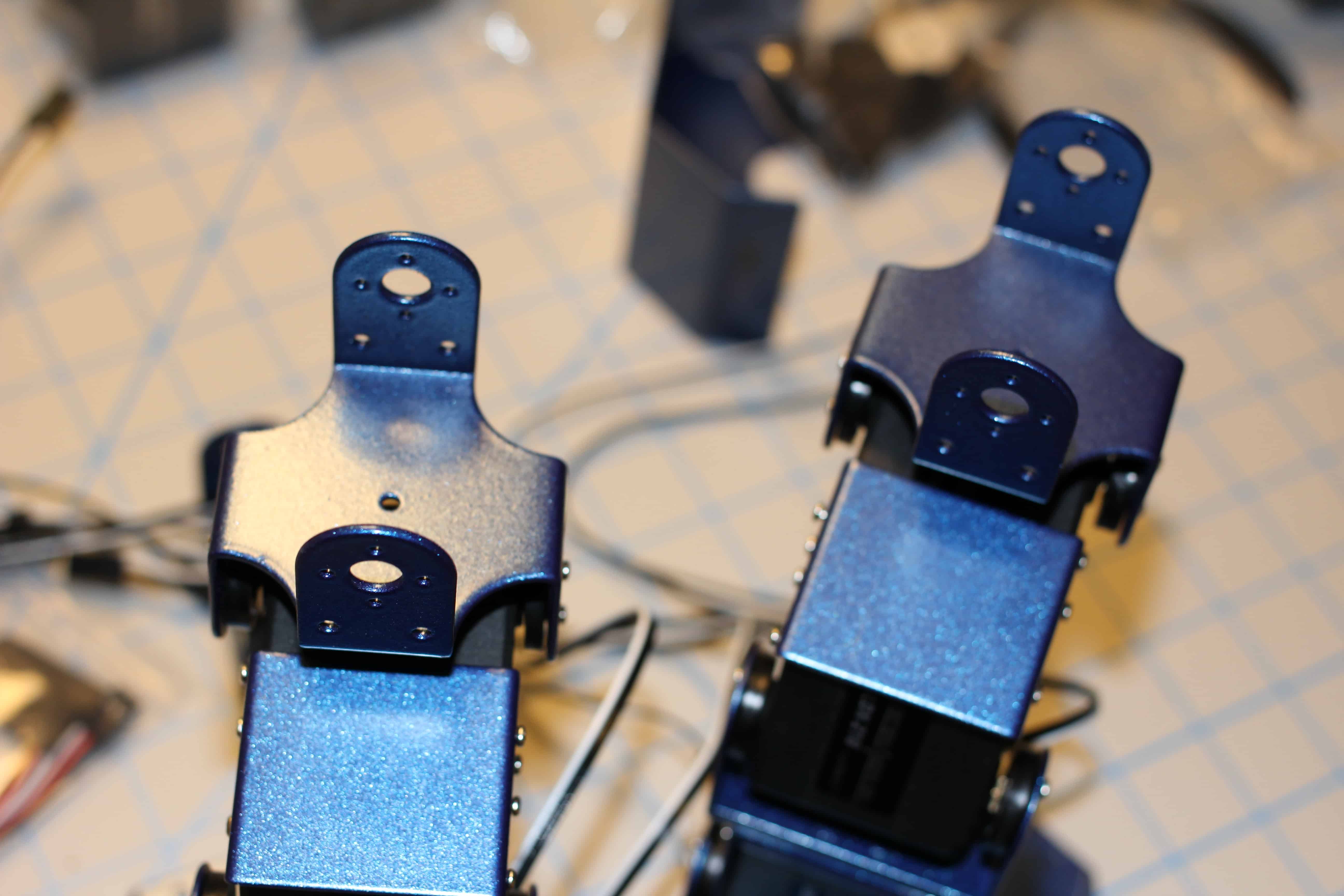
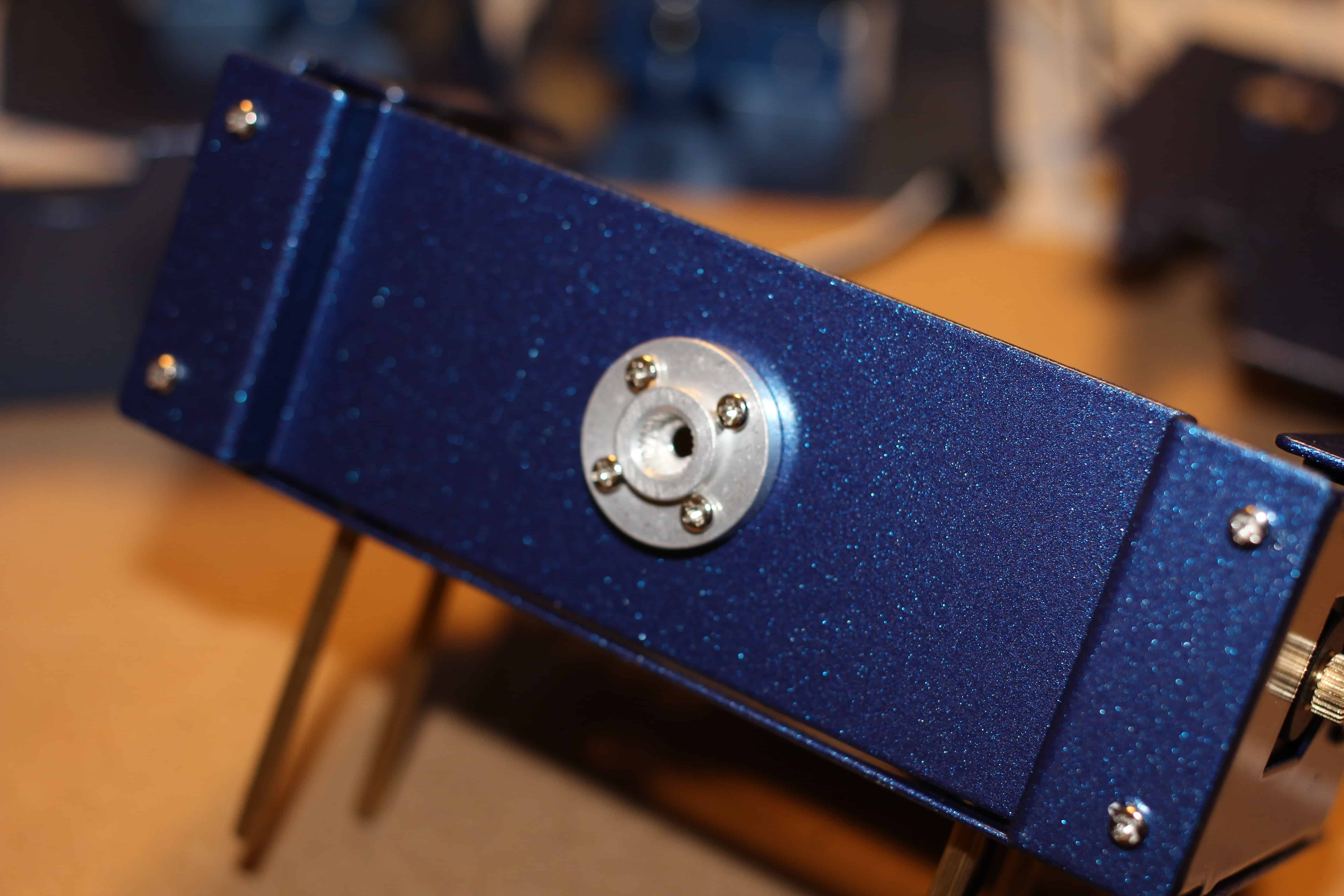
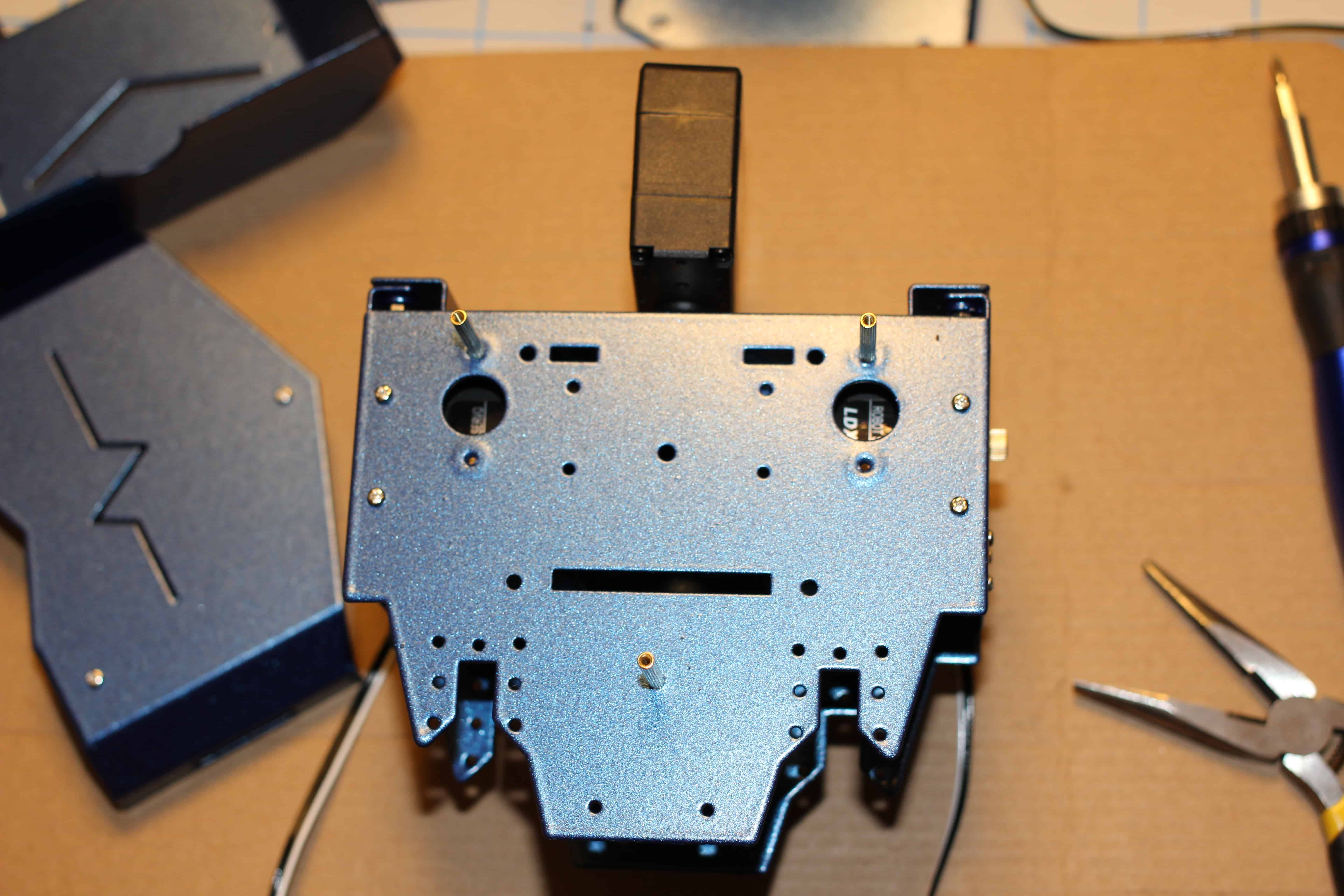
2. The chassis was originally white I used three coats of Rustoleum self etching primer and then three coats of Rustoleum Metallic Blue. Allow at least 3 days for paint to dry outdoors and fully off-gass.
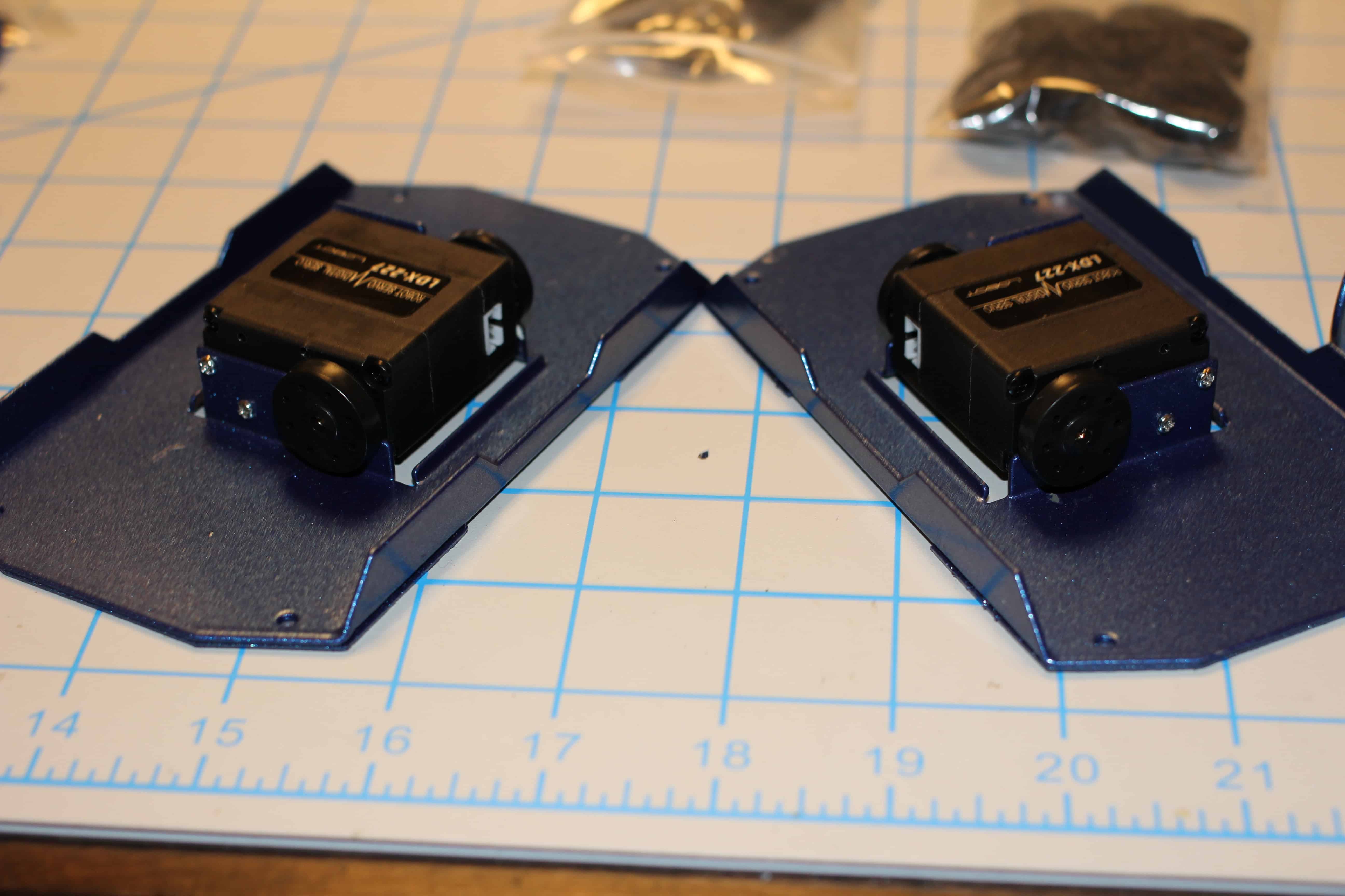
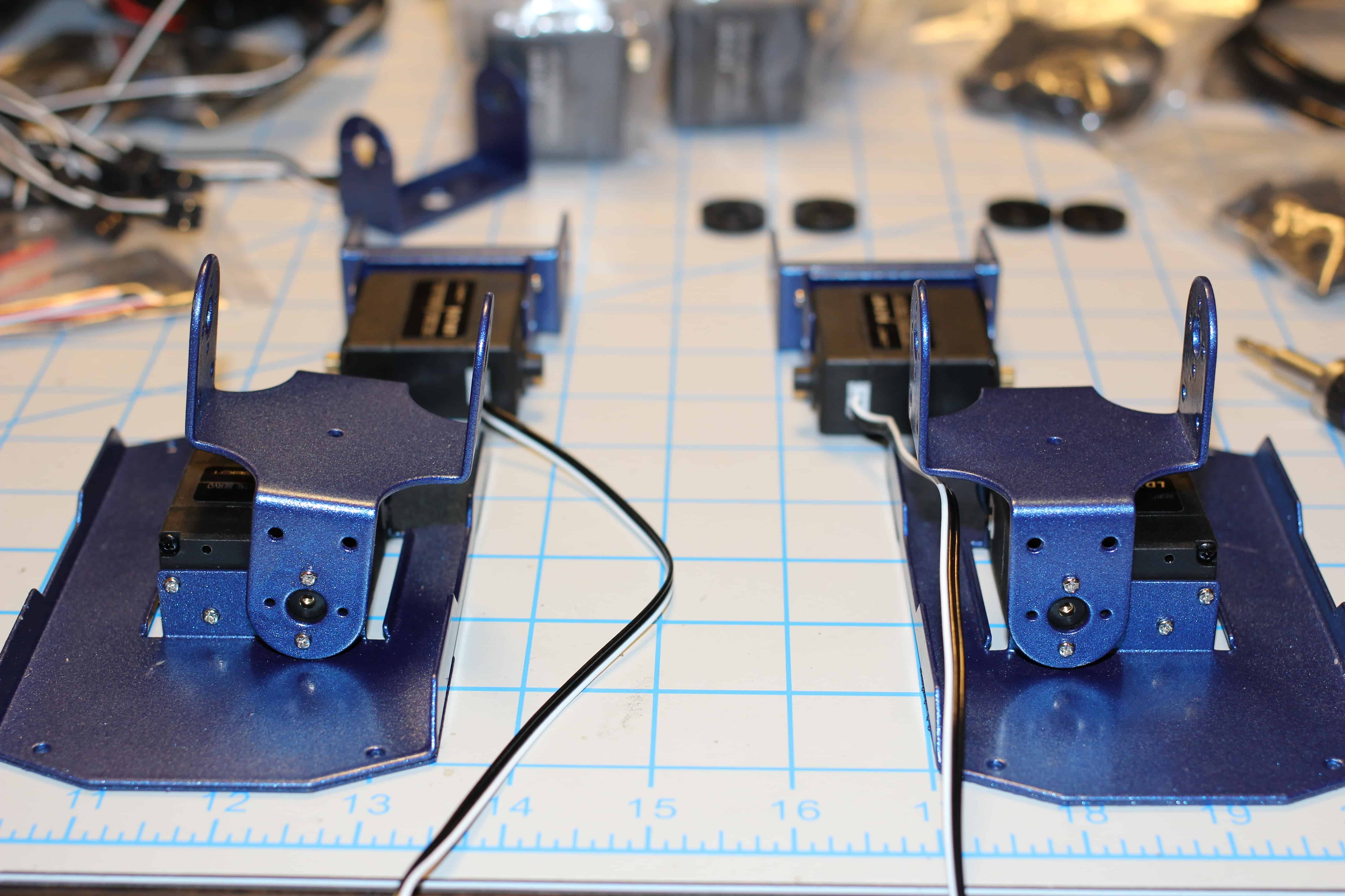
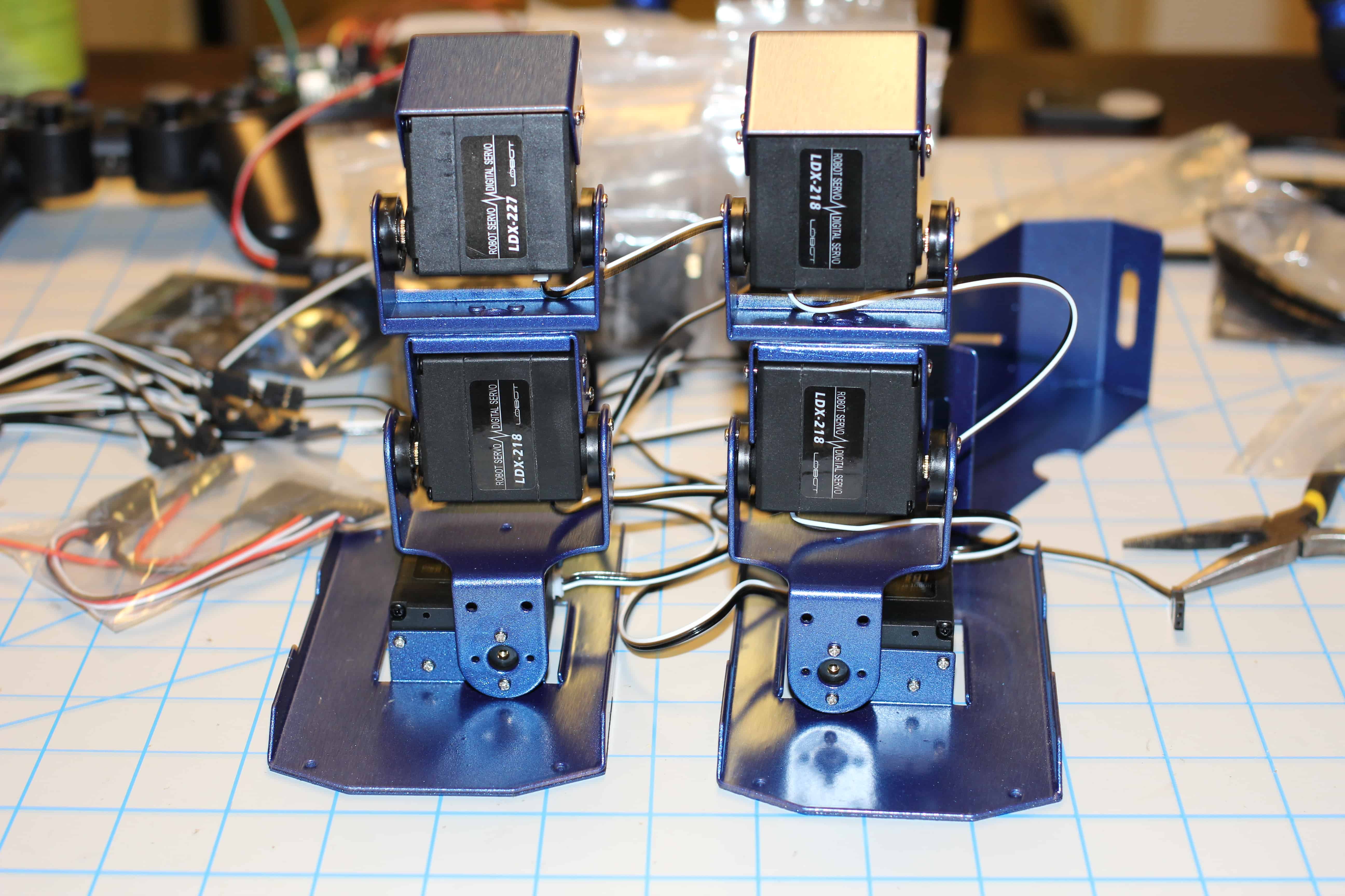
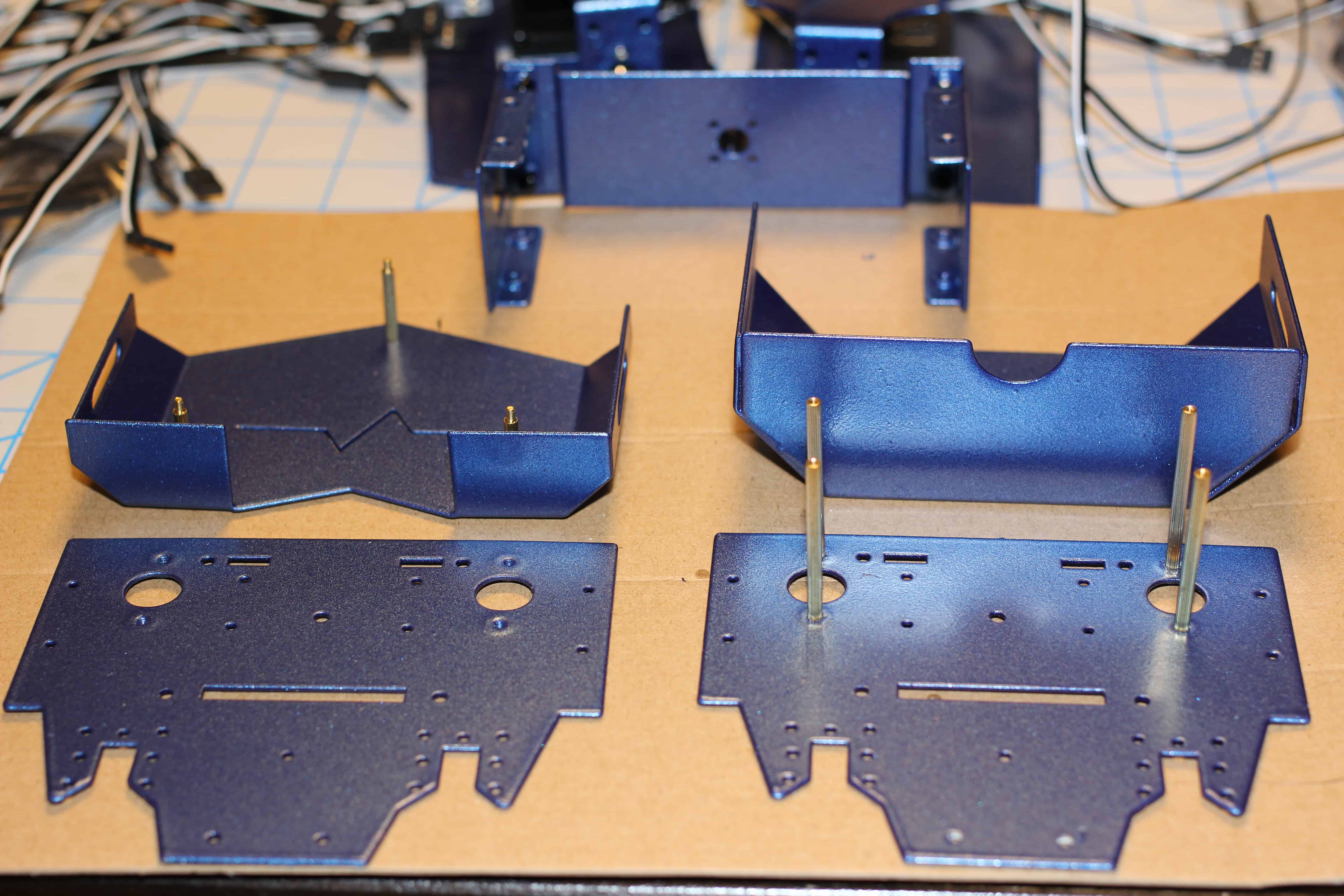
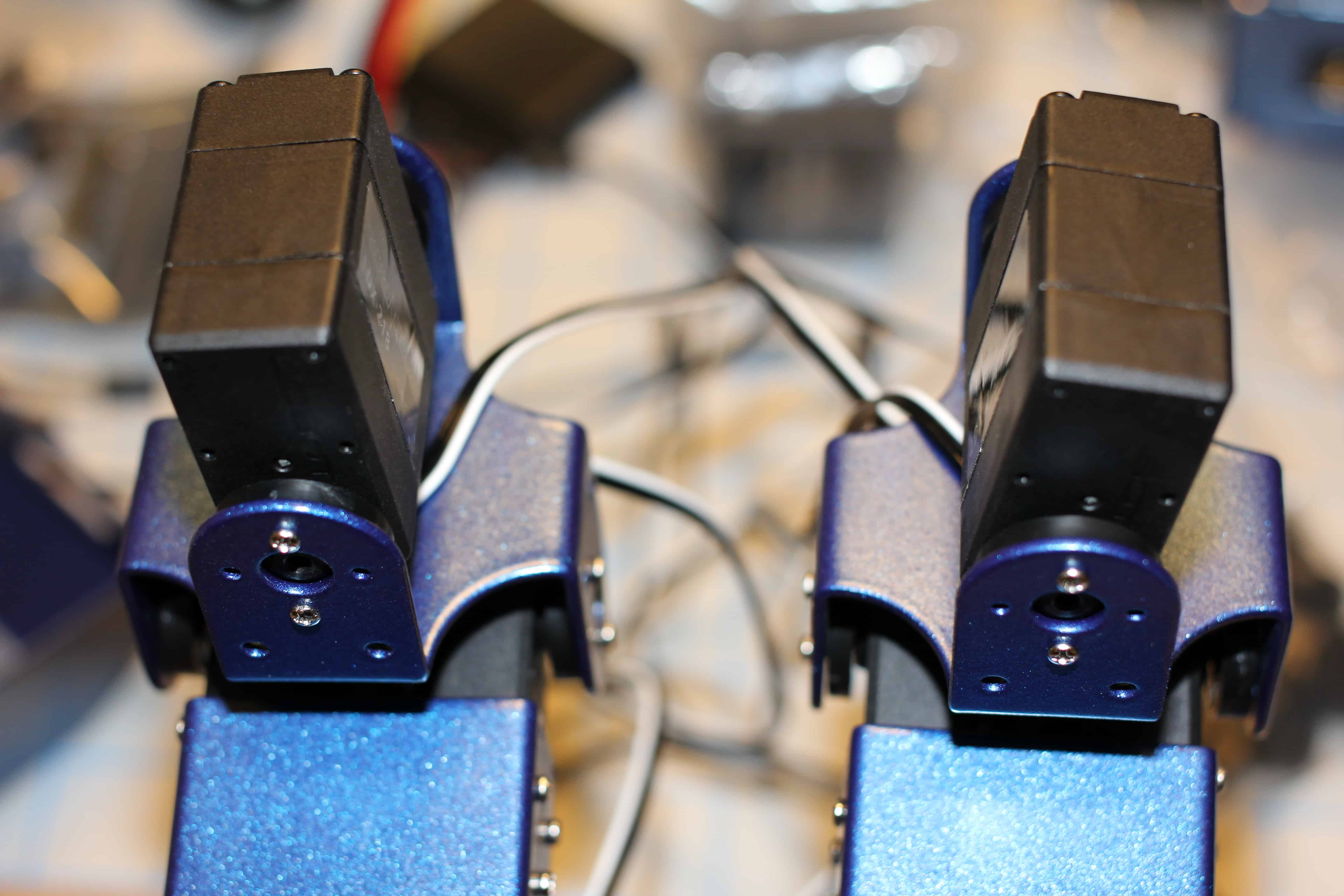
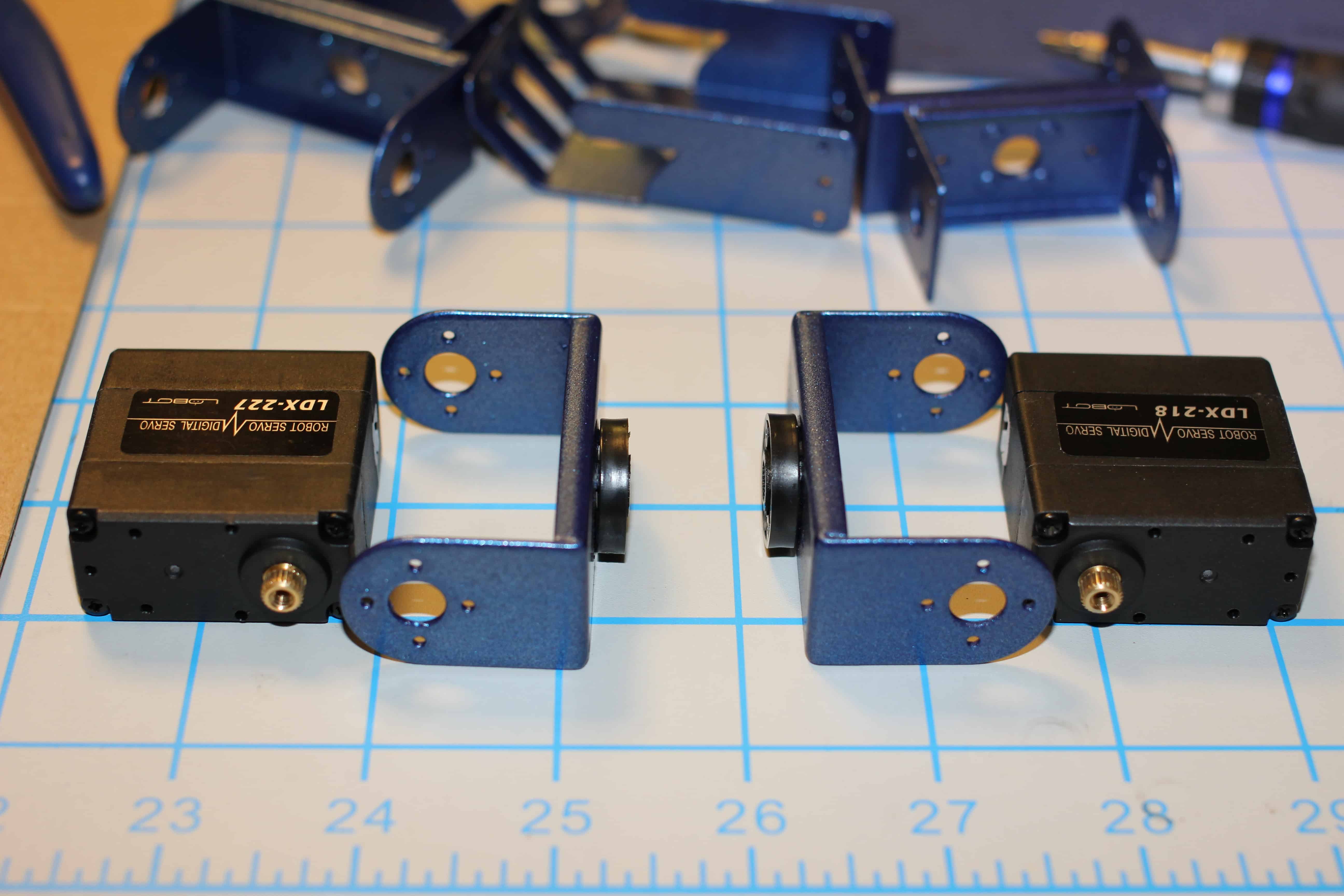
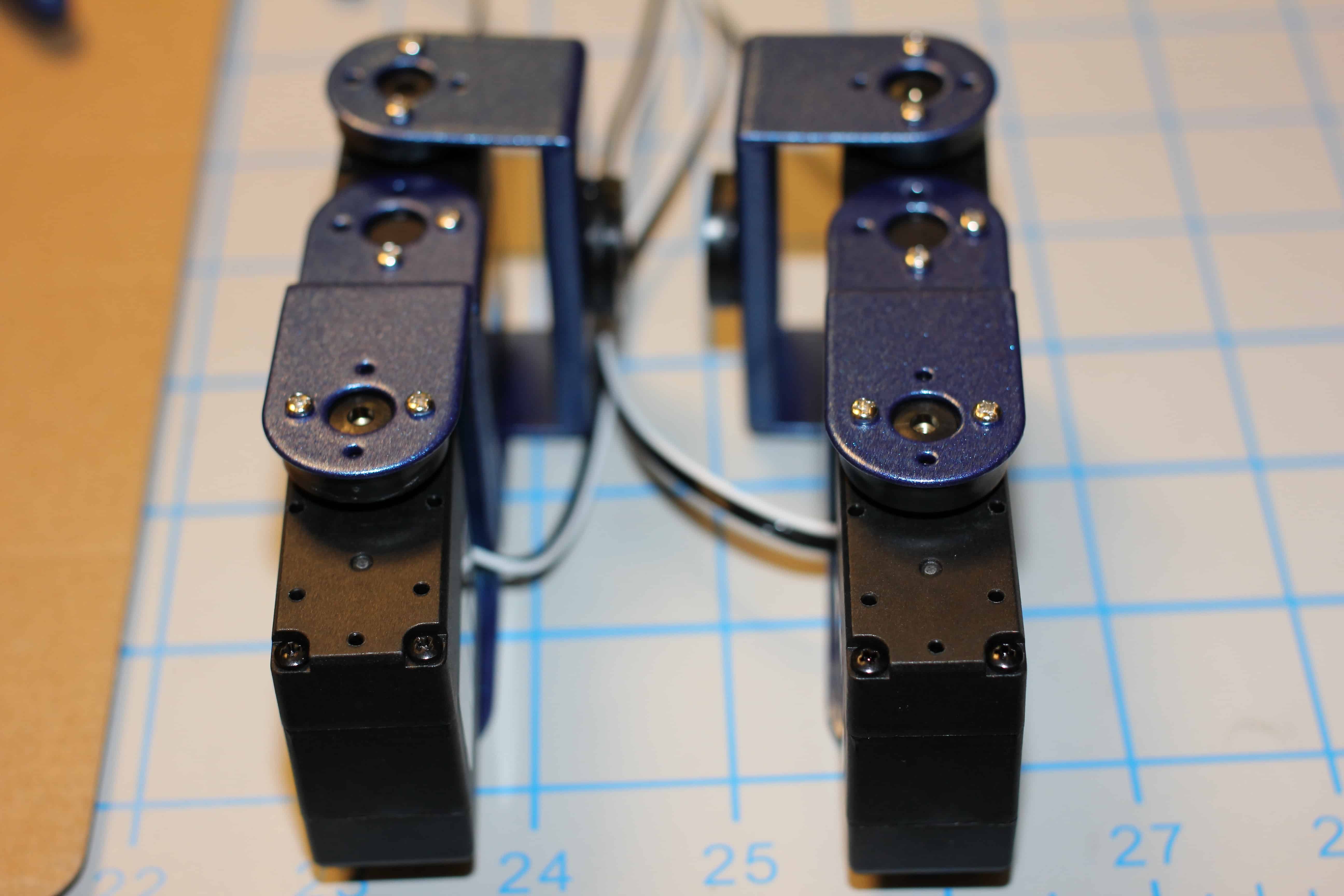
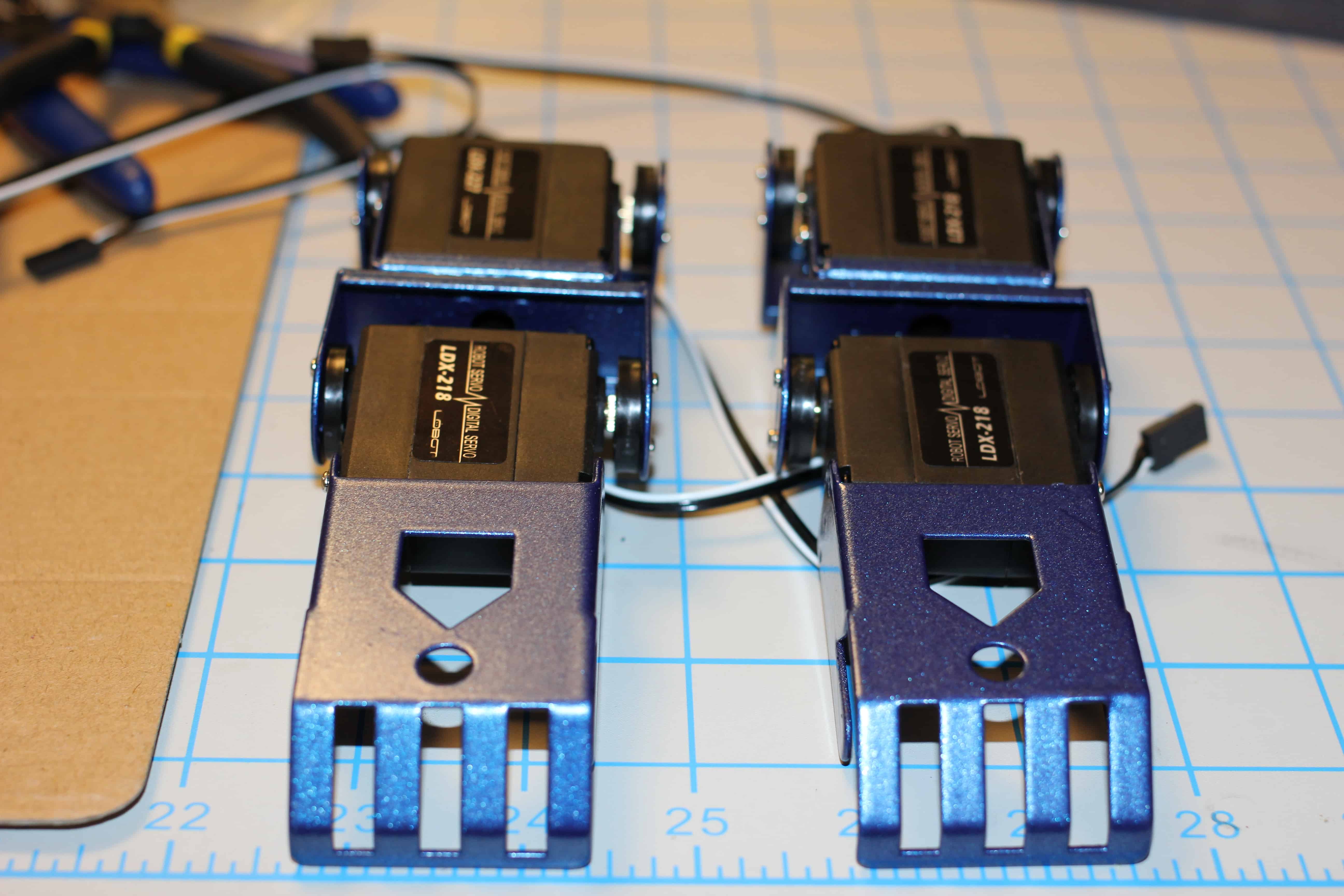
3. Laying out the feet and servos.
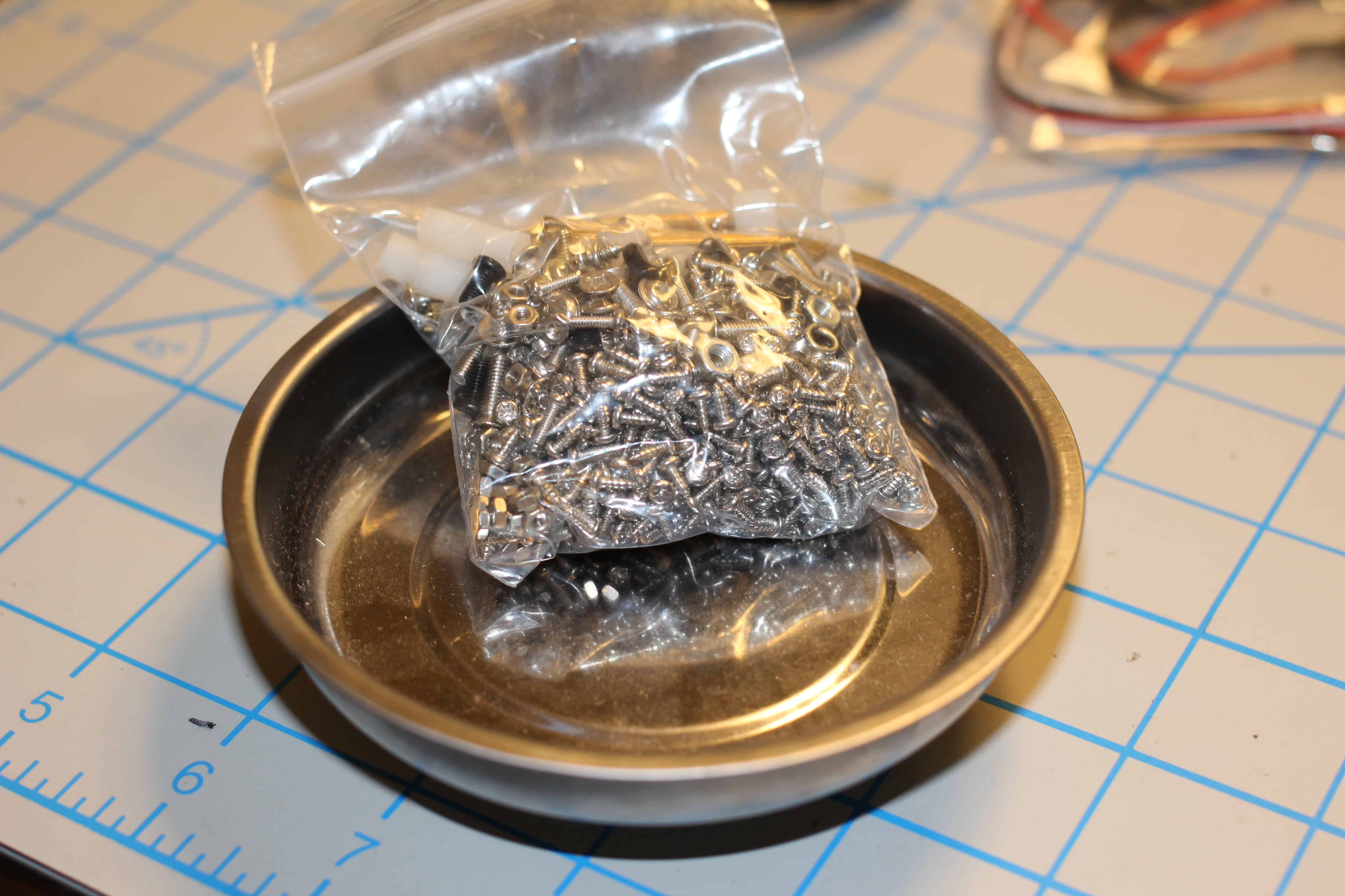
4. Dumping provided hardware into magnetic tray for easier searching.
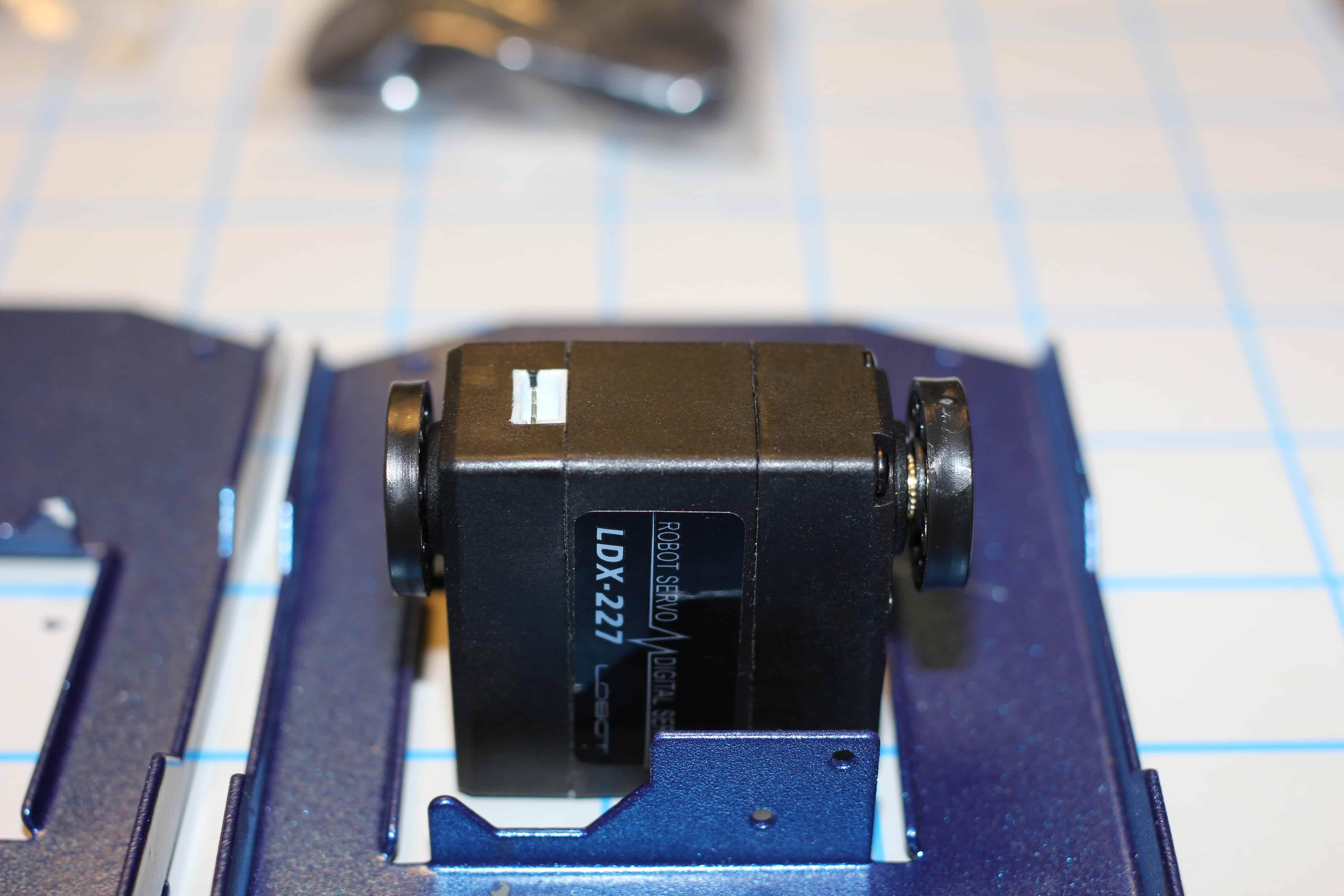
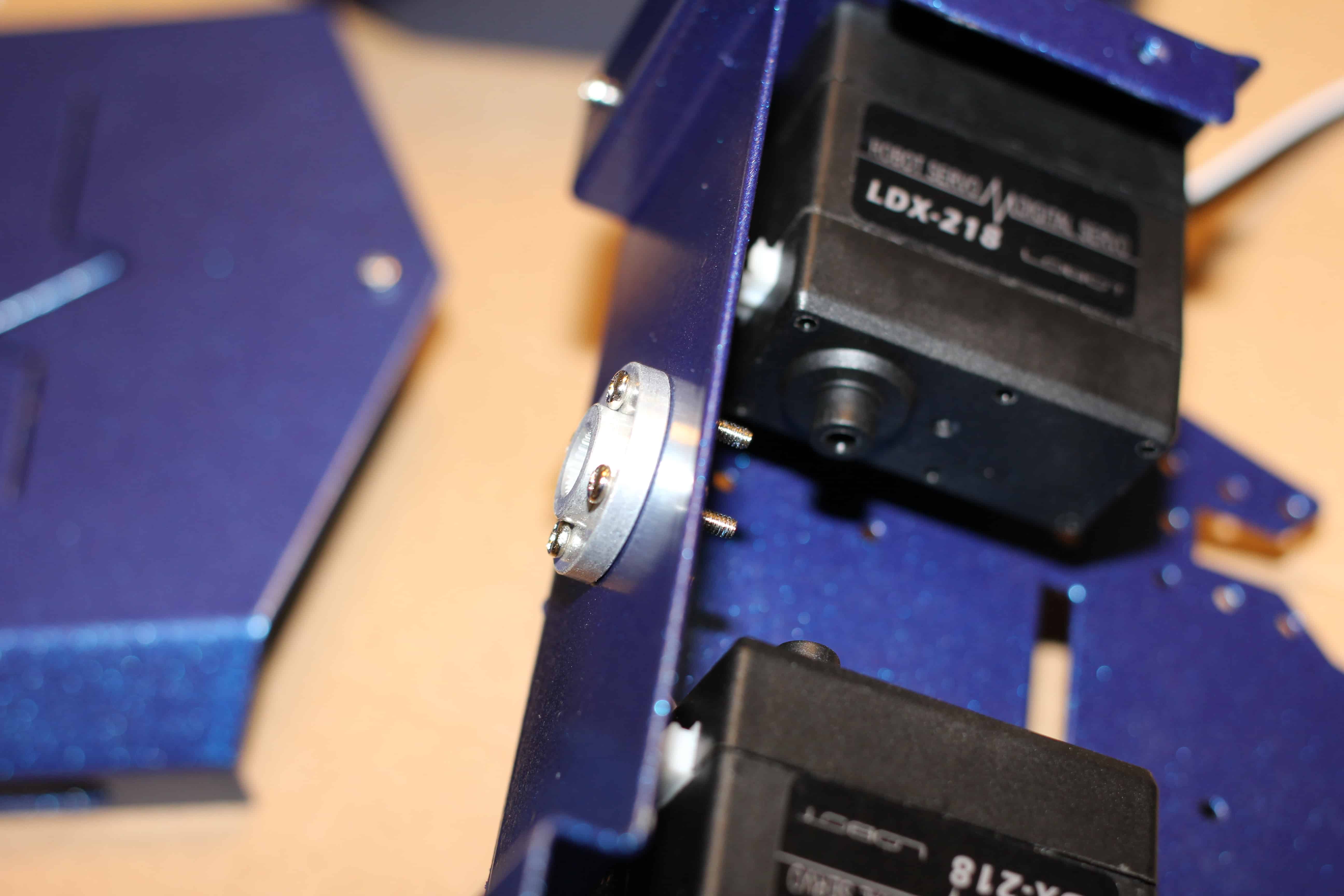
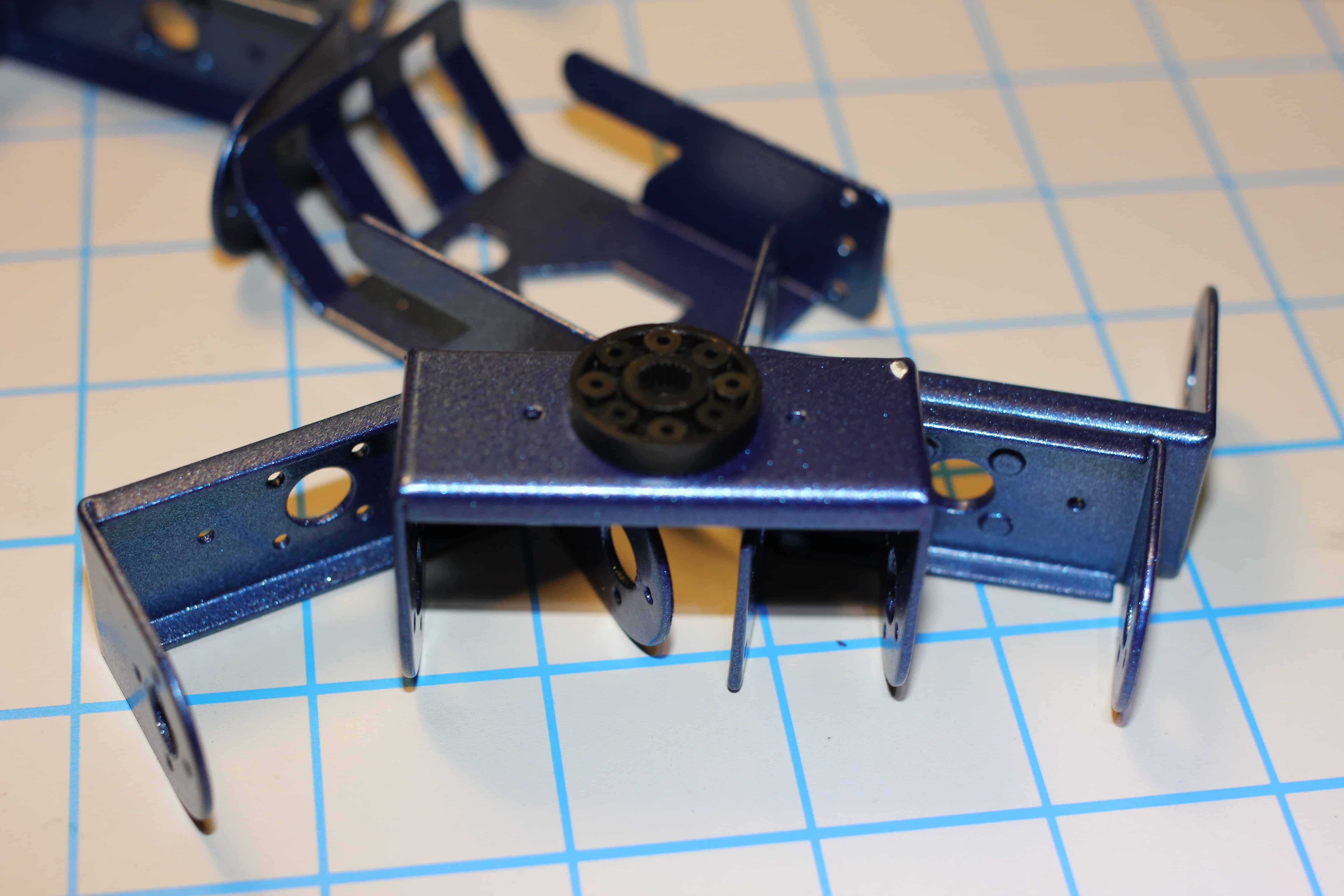
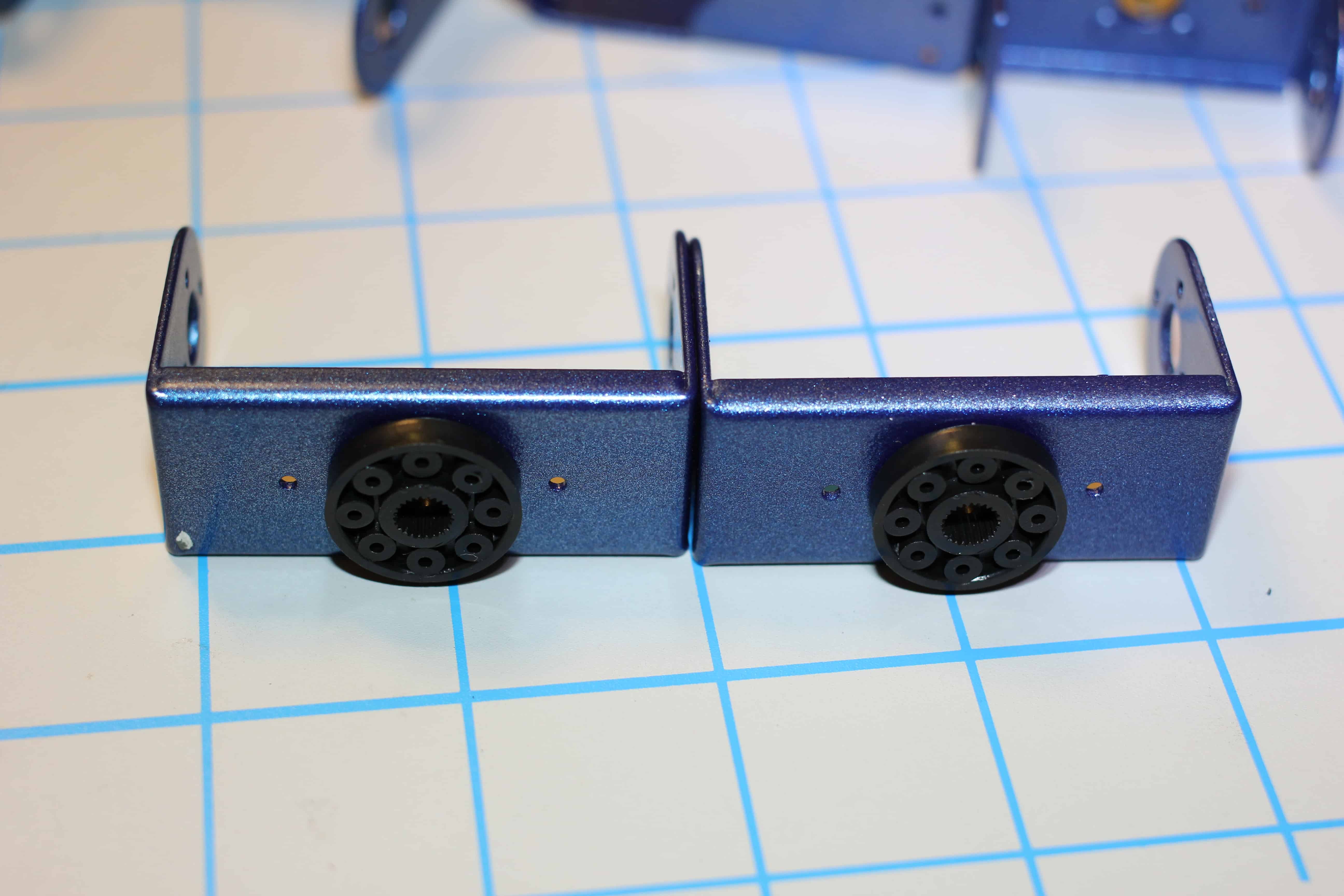
5. Two servo discs provided in kit, discs with teeth attach to sprocket.
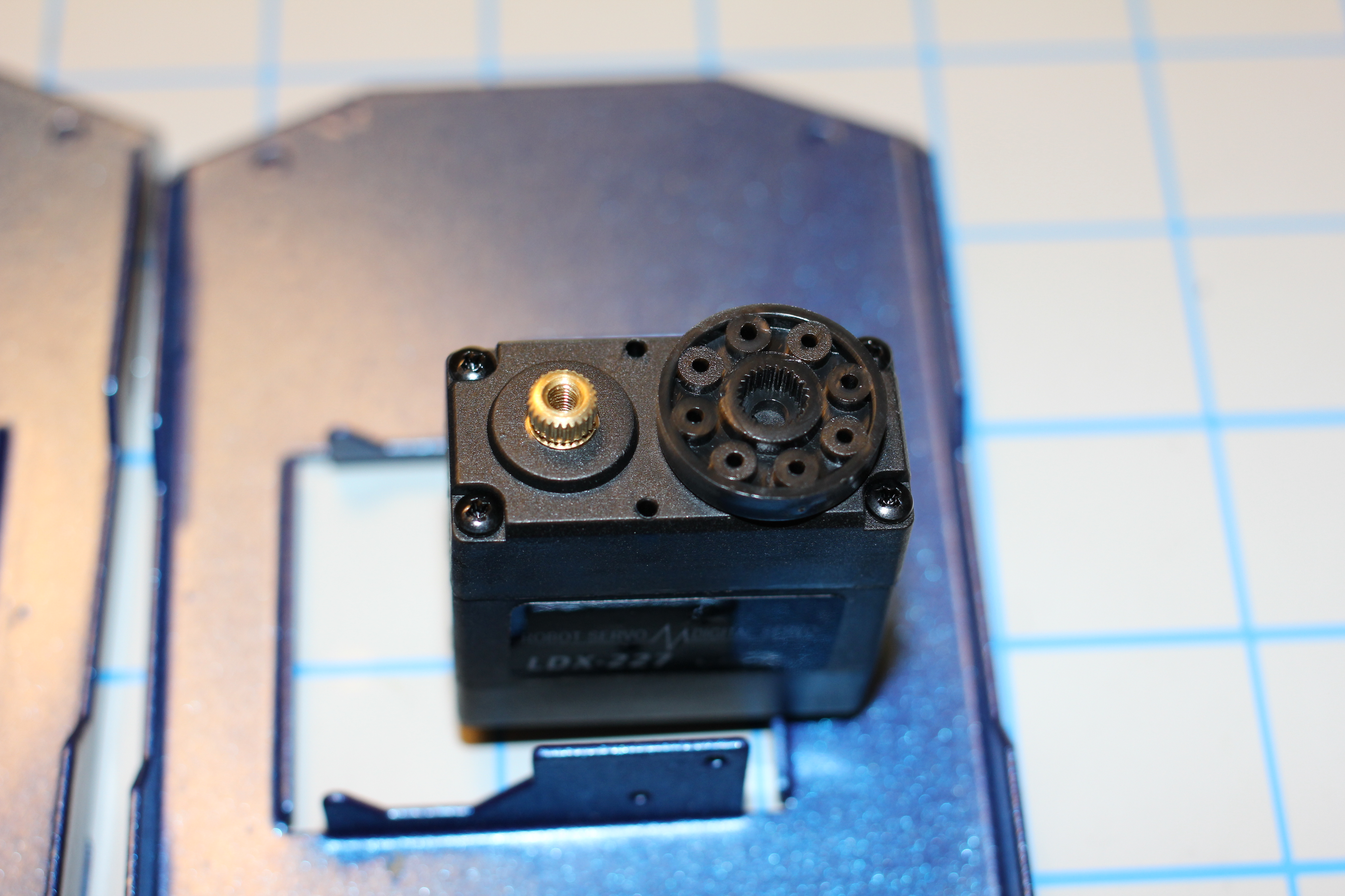
6. Smooth disc attaches to opposing side.
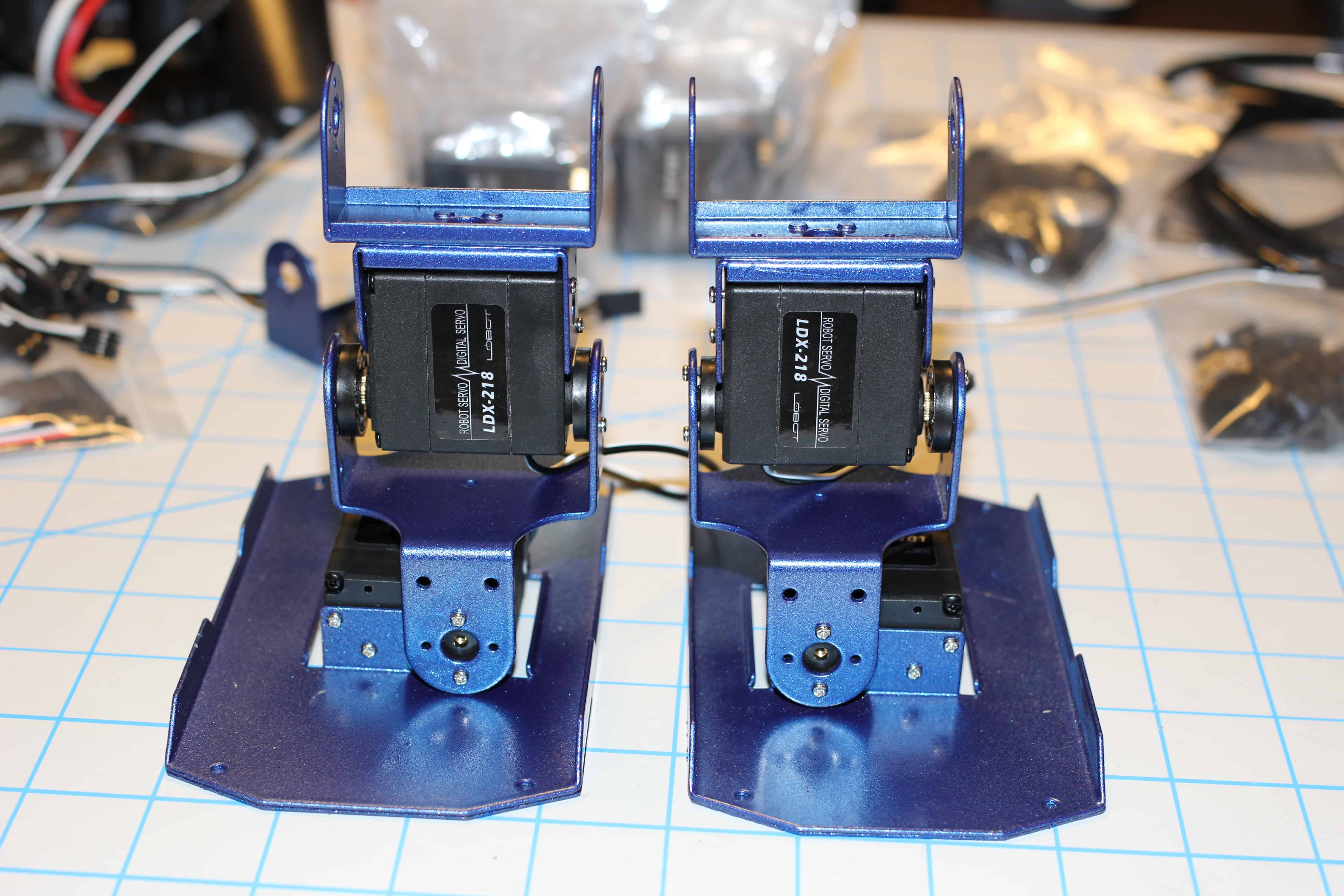
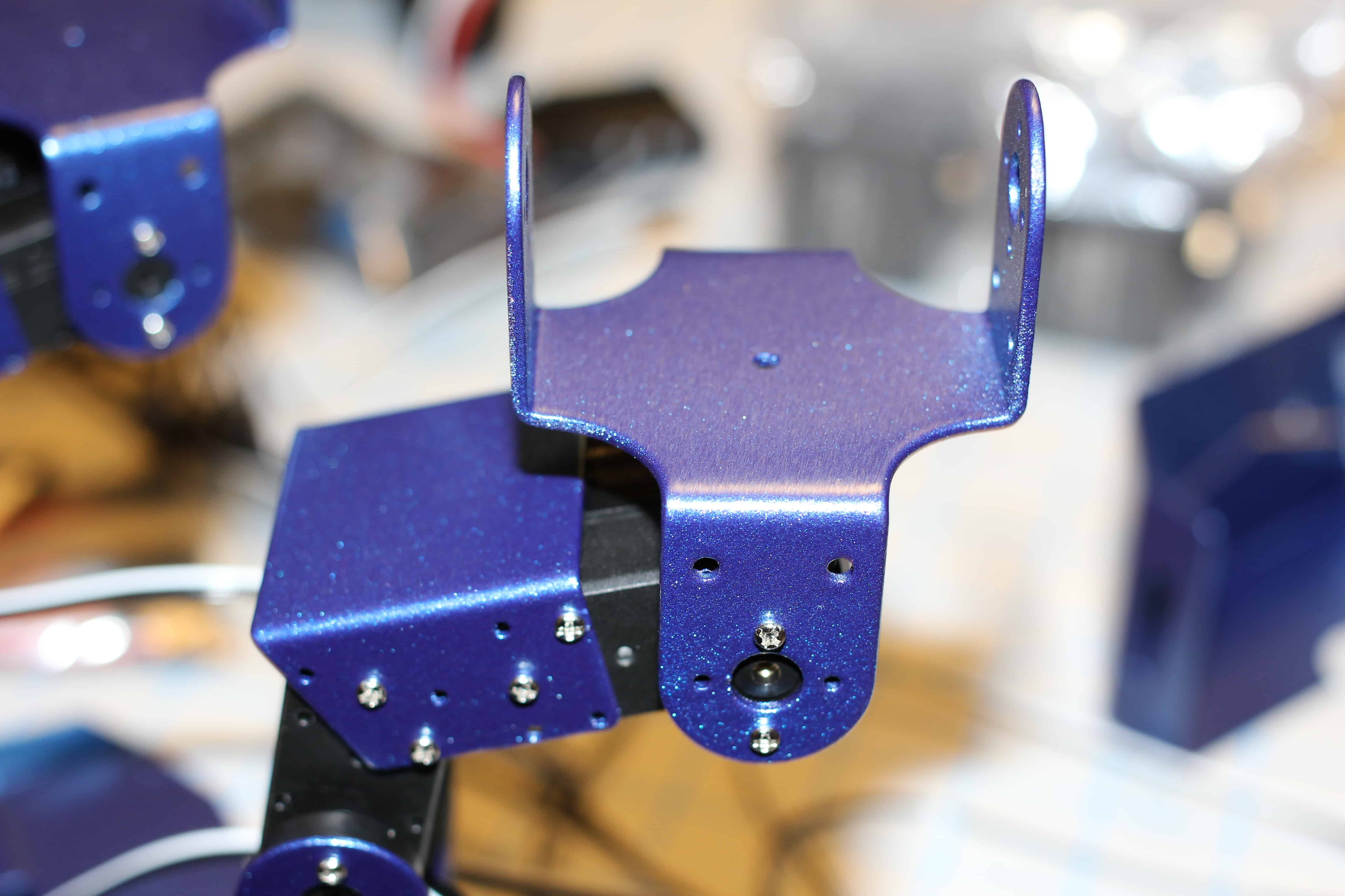
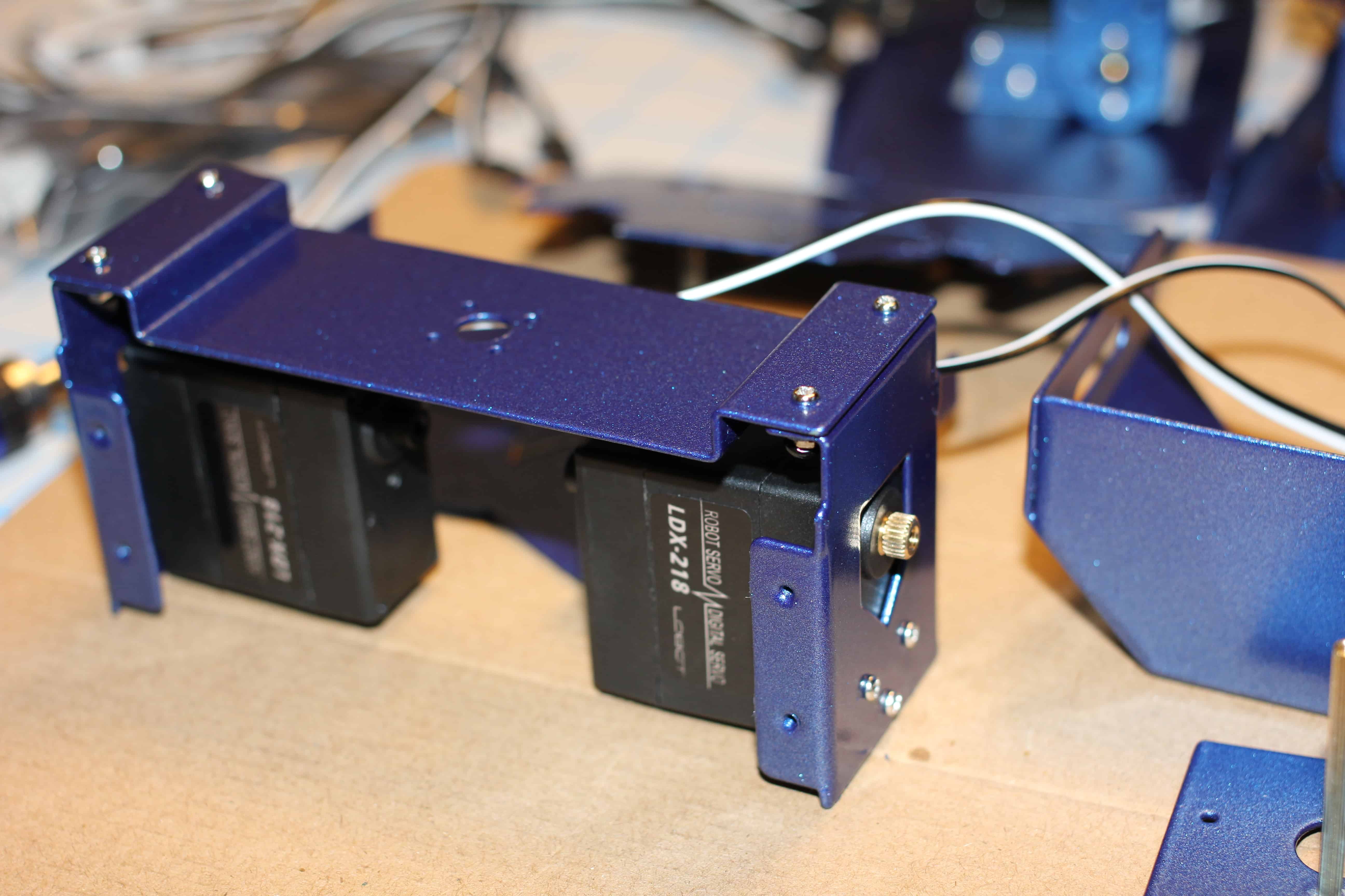
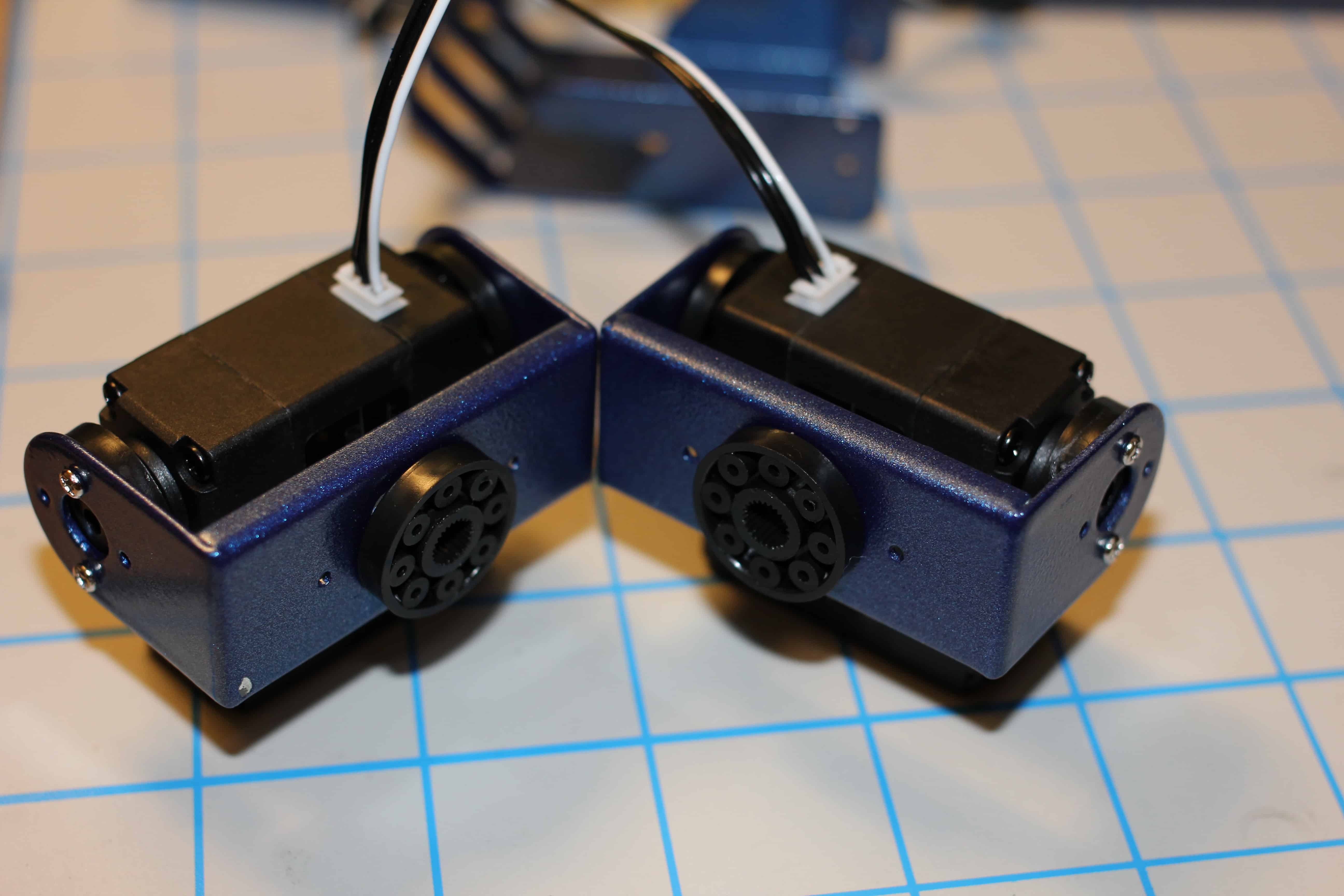
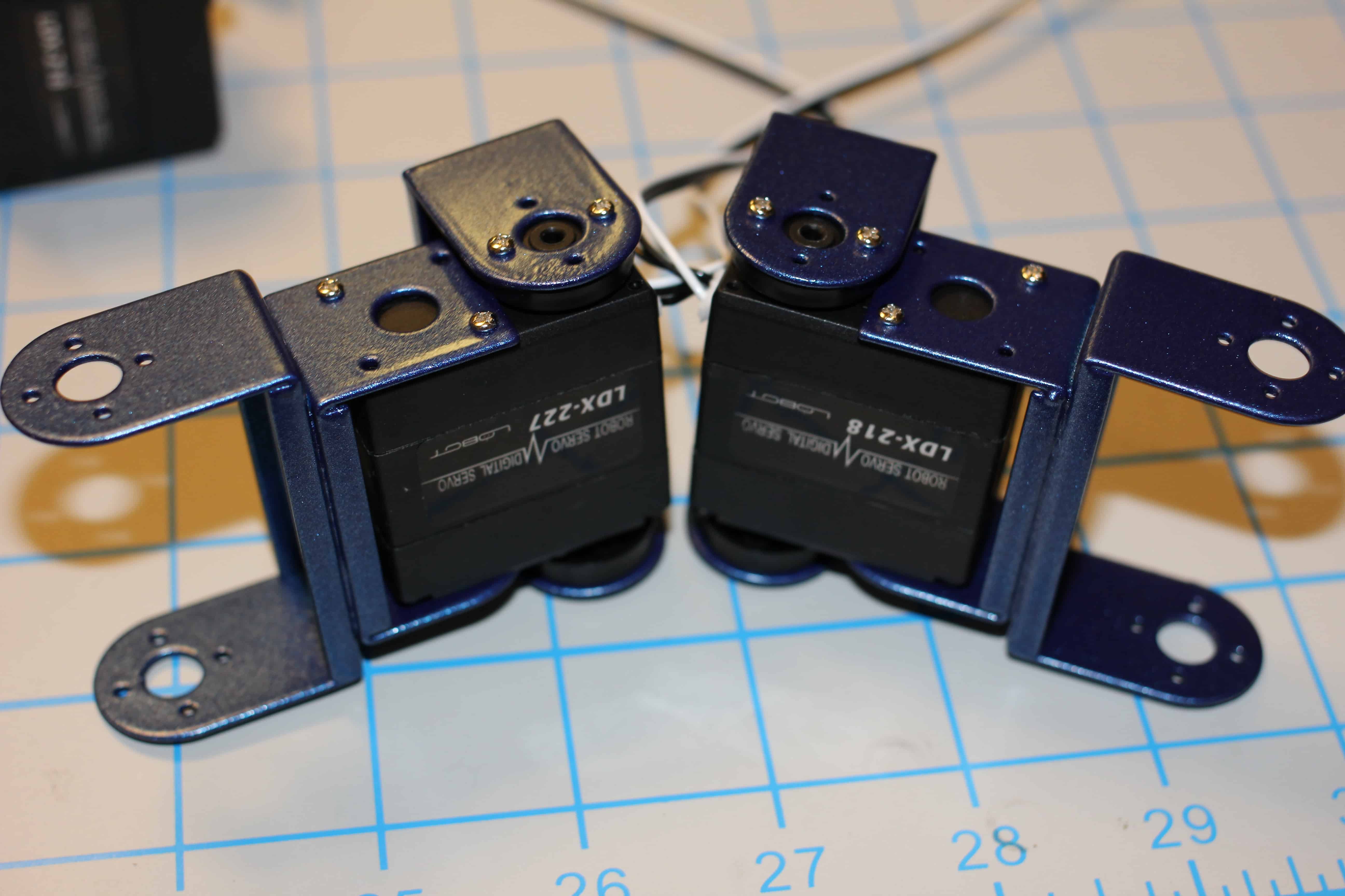
7. Attached servo to feet. I only screw-in two screws as it will be easier to disassemble, just in case I make an error or find out later that the servo is not centered. You can always go back and tighten later. Also another pro-tip, attach the servo cables before screwing them in place, as they may become inaccessible later in the build-process.
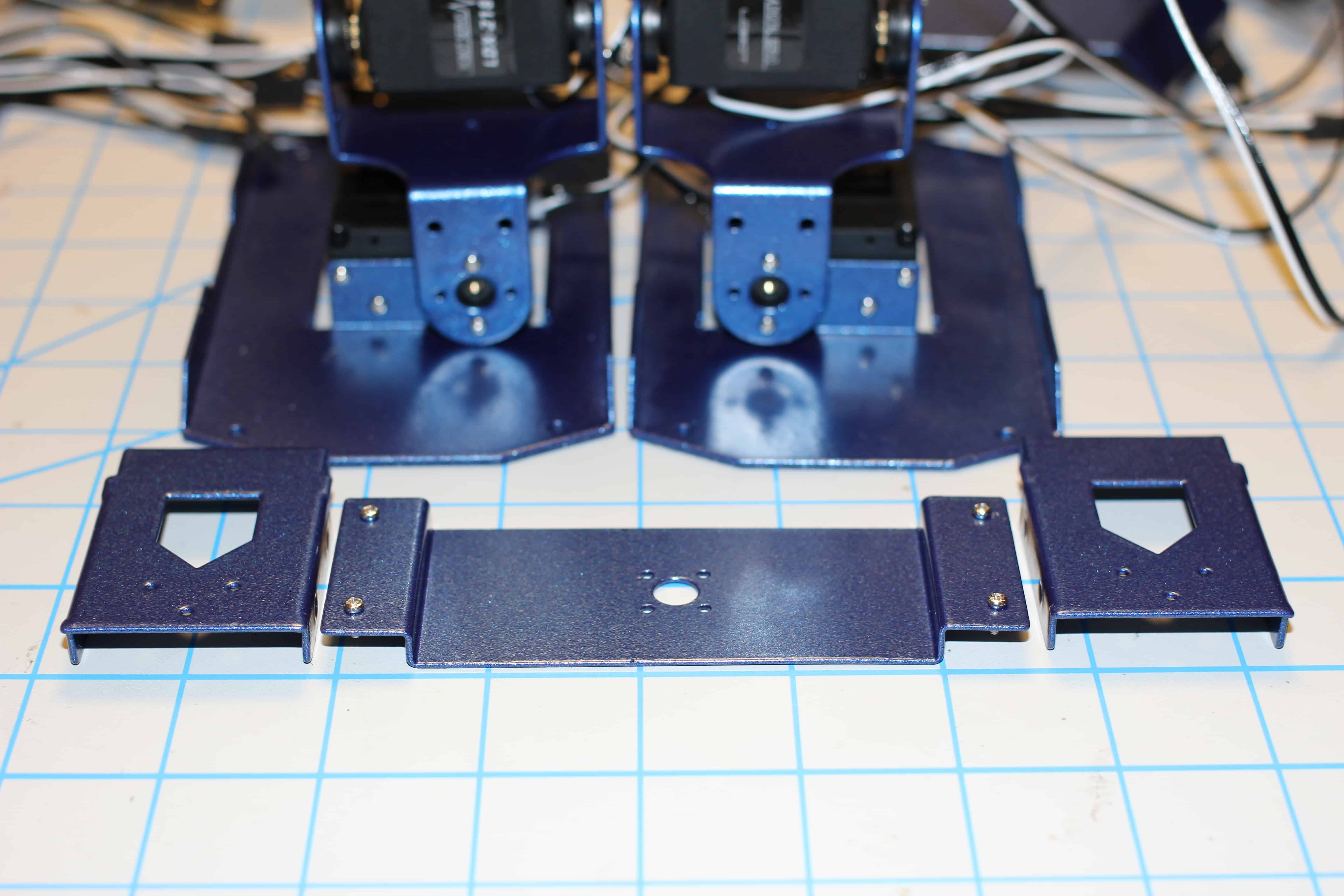
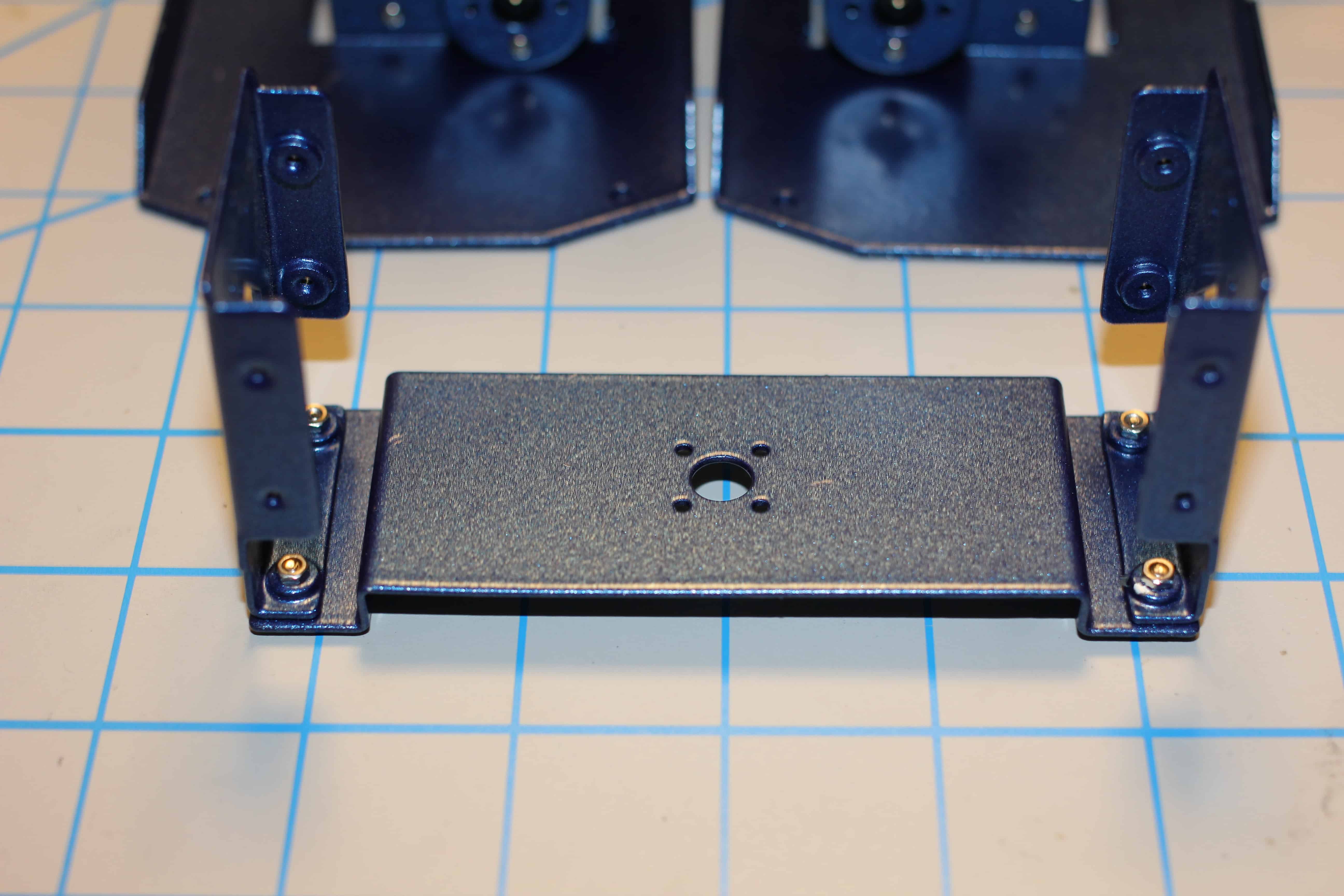
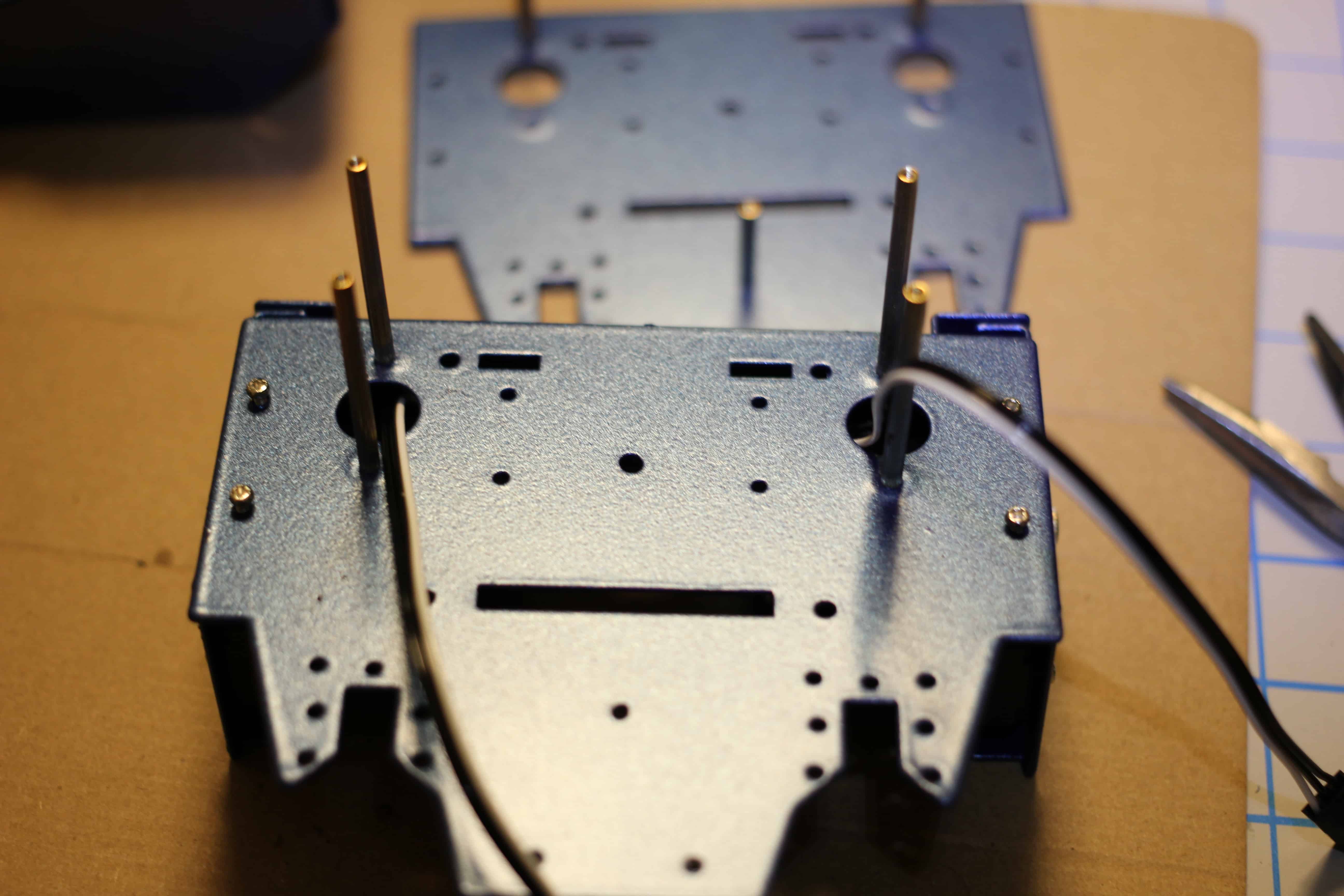
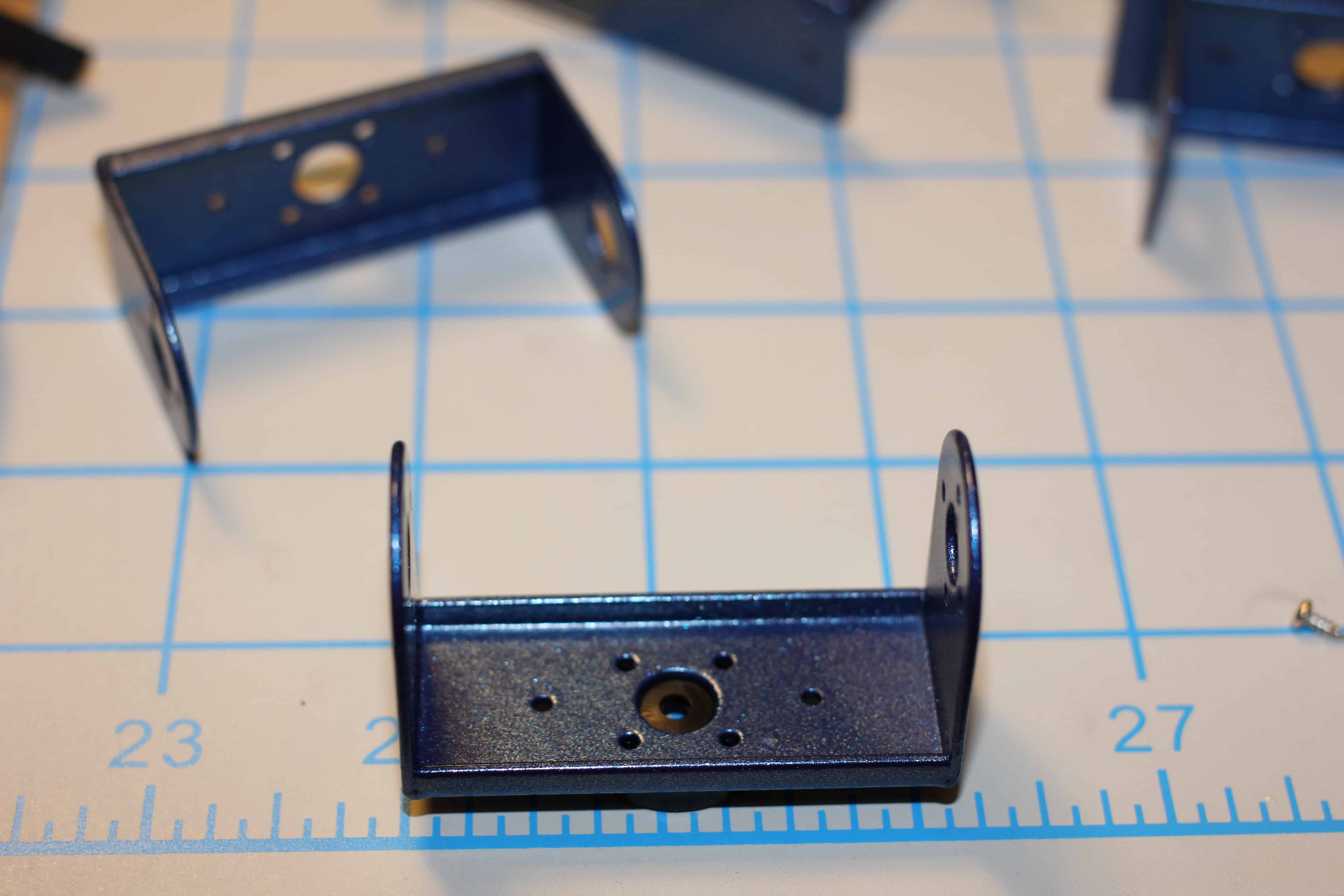
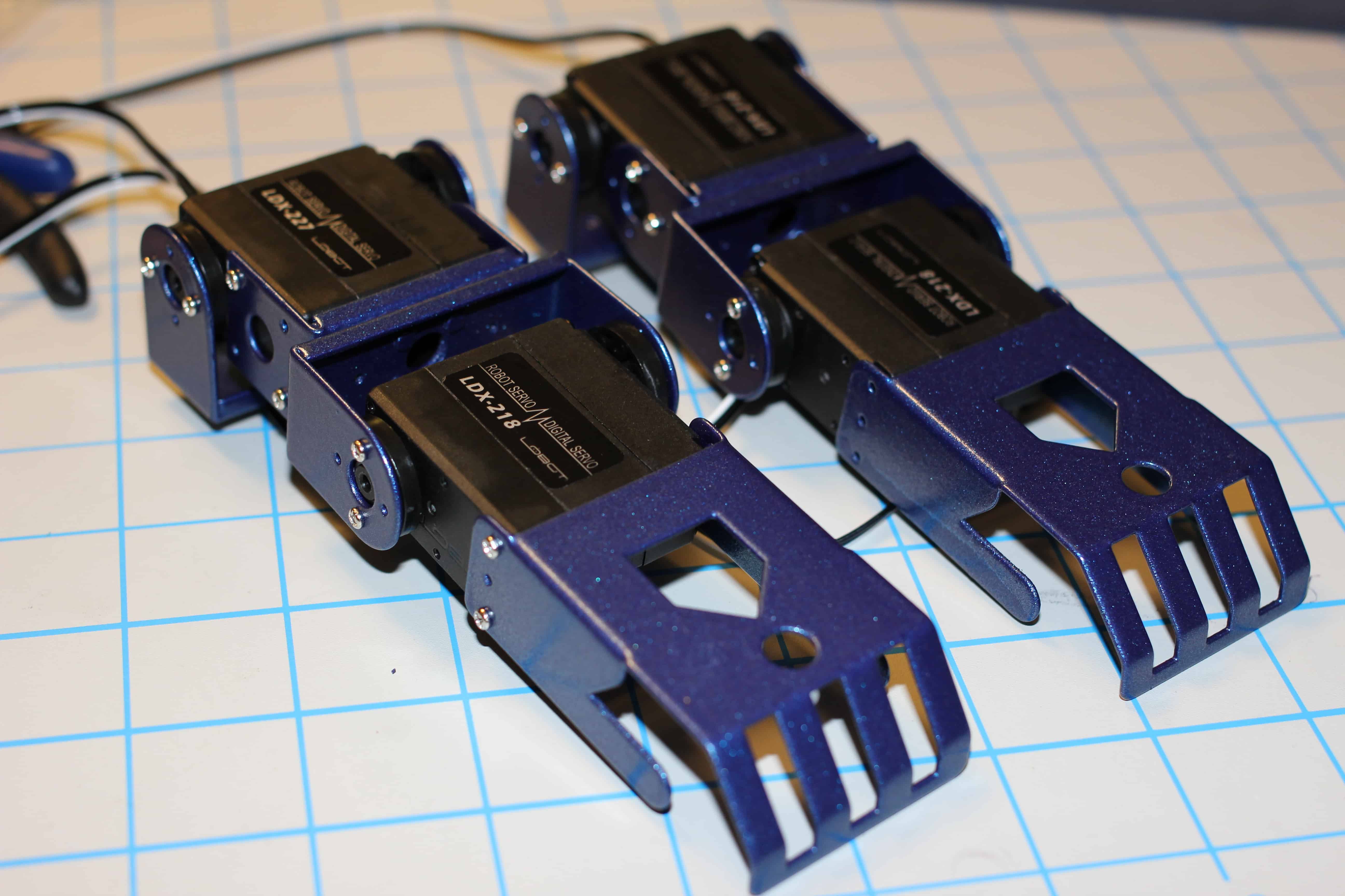
8. Setting up the “shins” of the robot.
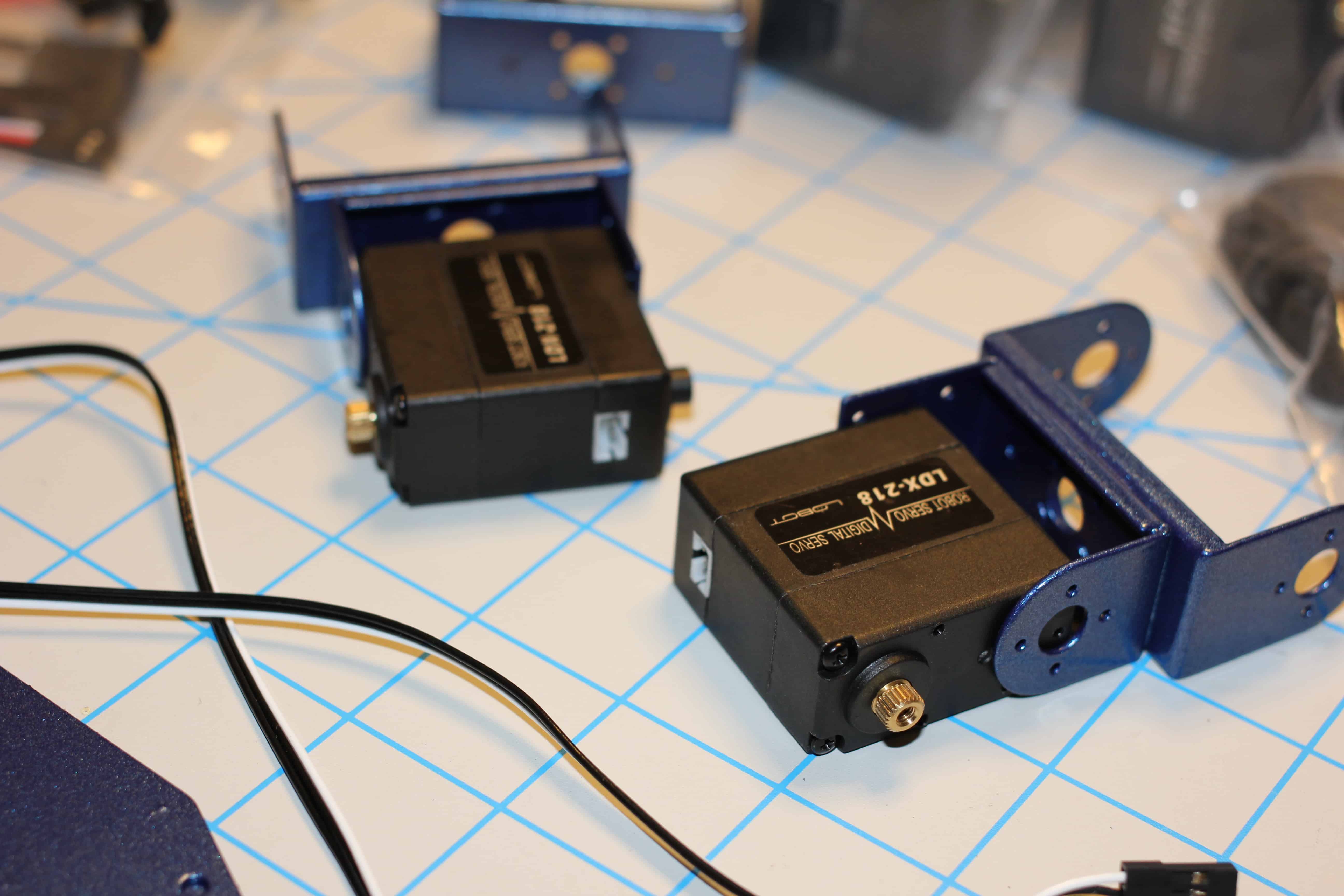
9. Attached the shin-receiver to the feet.
10. Shins attached.
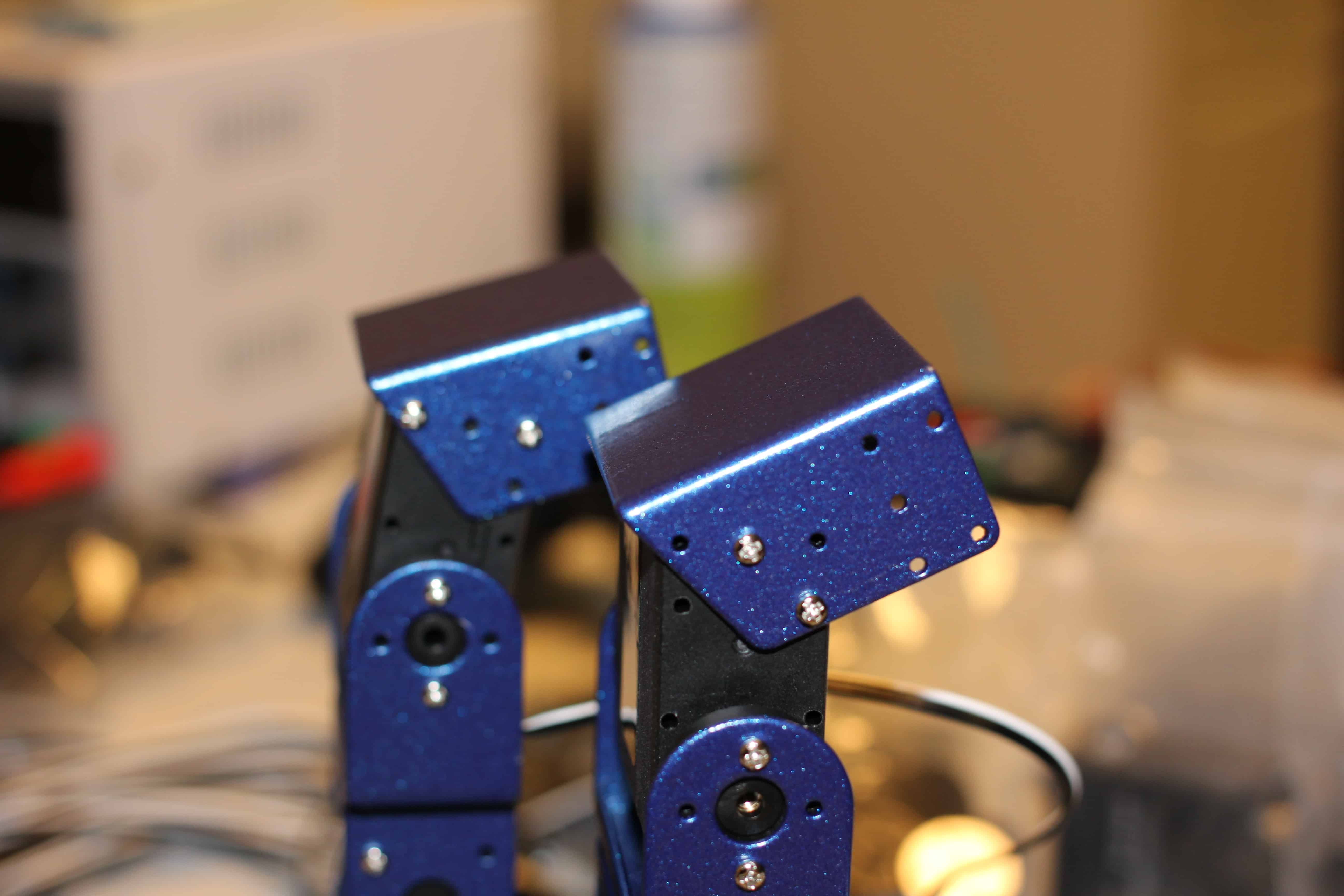
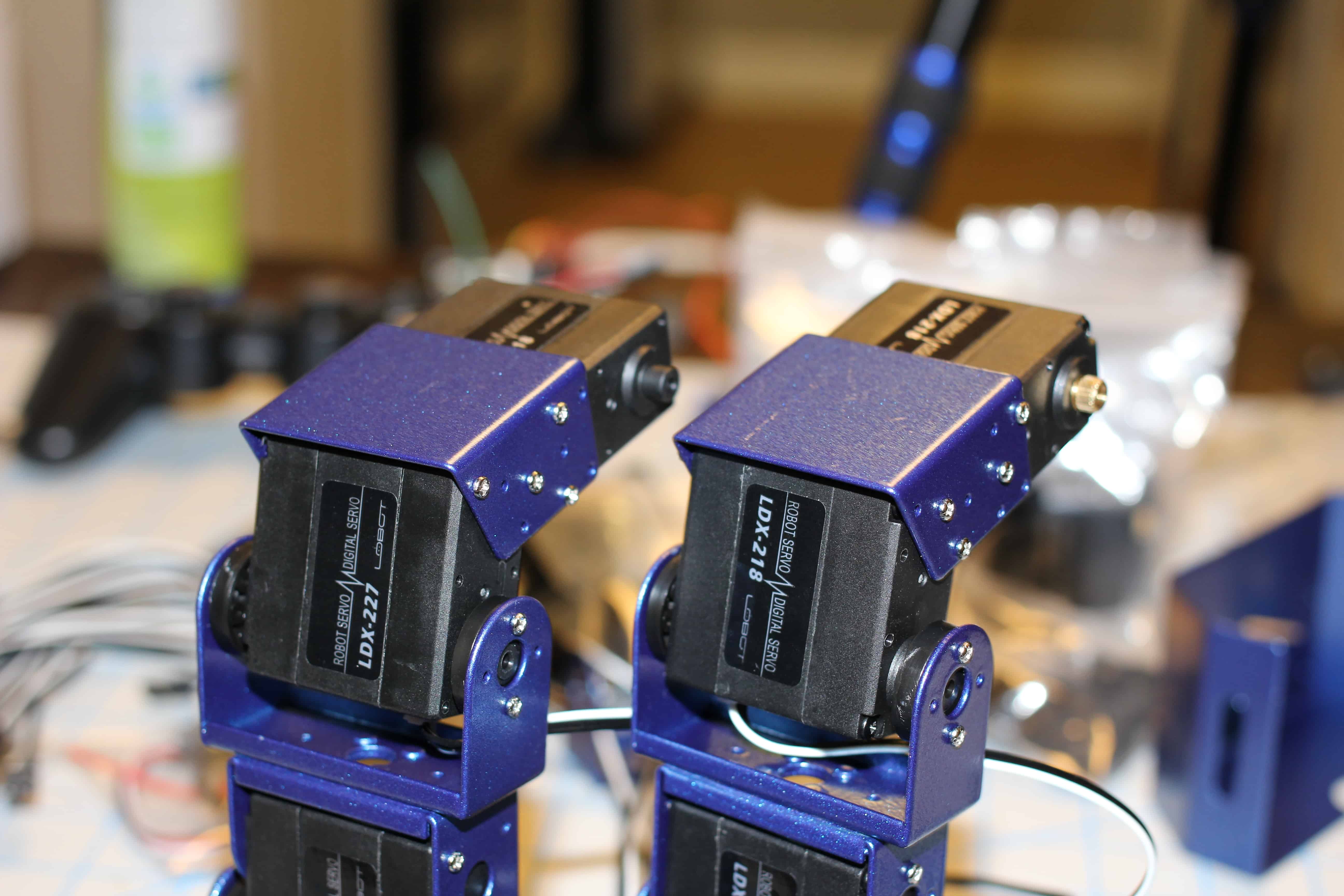
11. Knees setup.
12. Knees attached.
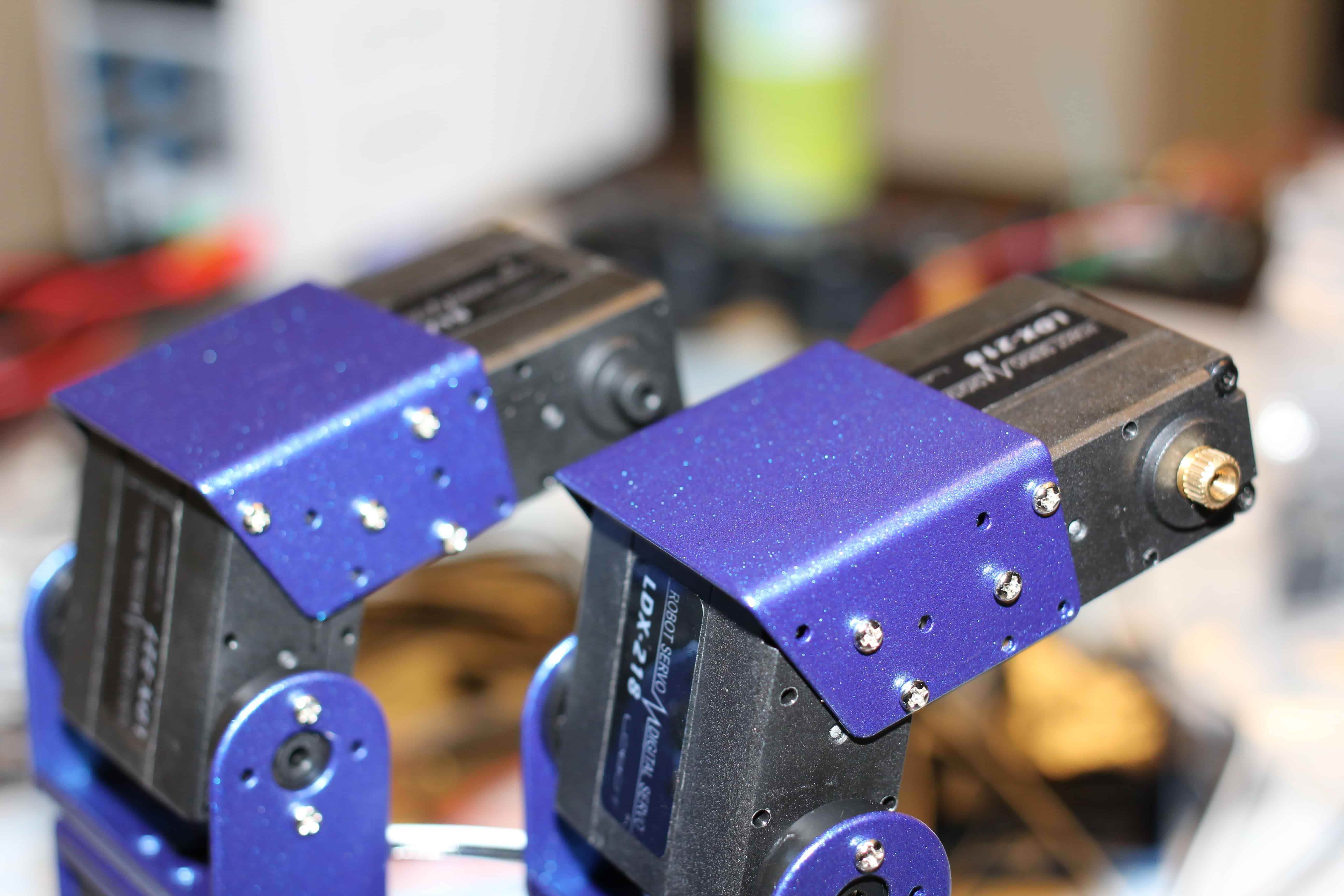
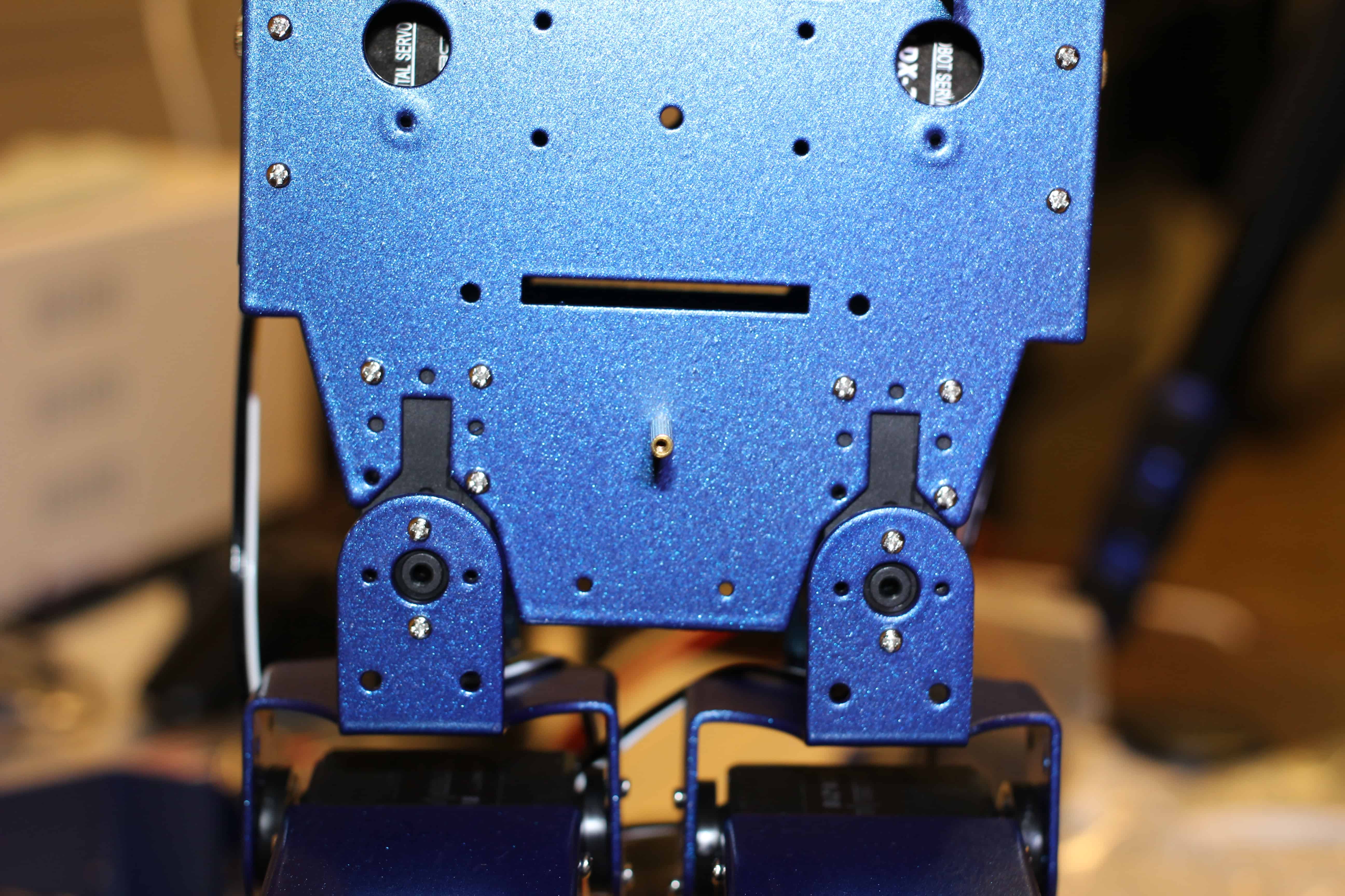
13. Hip-receiver attached.
14. Laying out collar-bone/shoulder assembly.
15. Collar-bone/shoulder assembly attached.
16. Laying out torso section.
17. Attached servos to make shoulder joints.
18. Attaching the back to the torso. Don’t attach the front just yet.
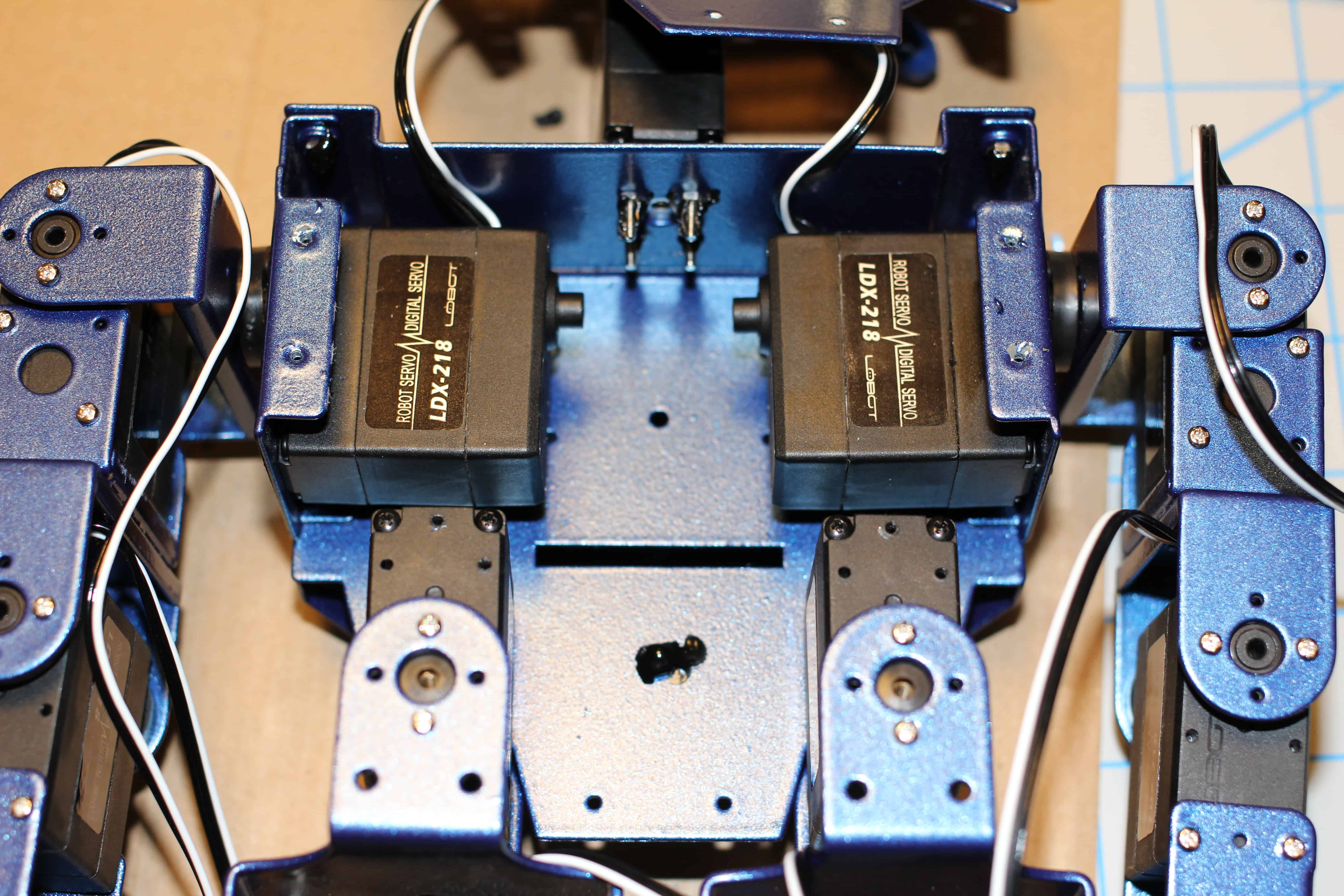
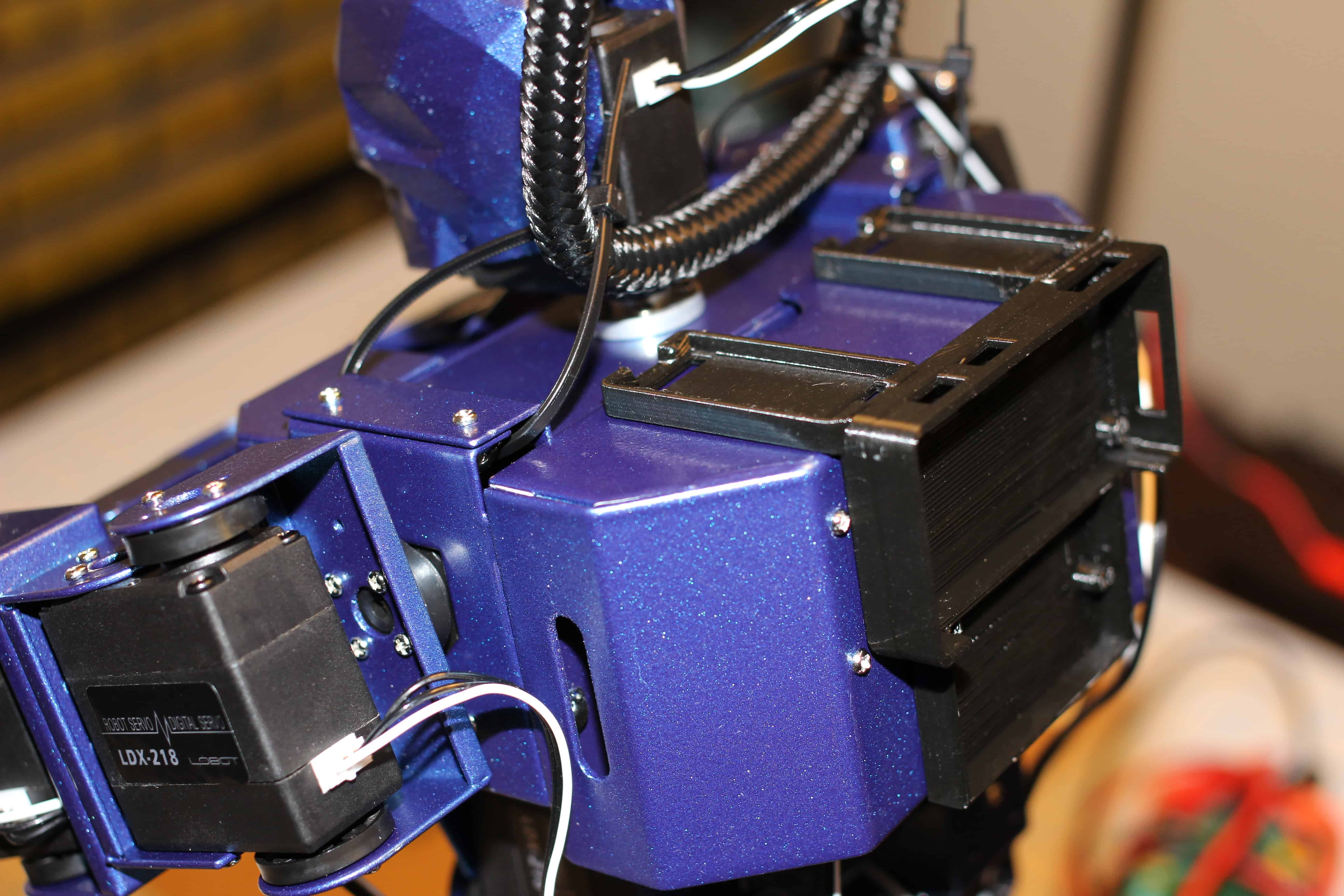
19. Neck Servo receiver attached.
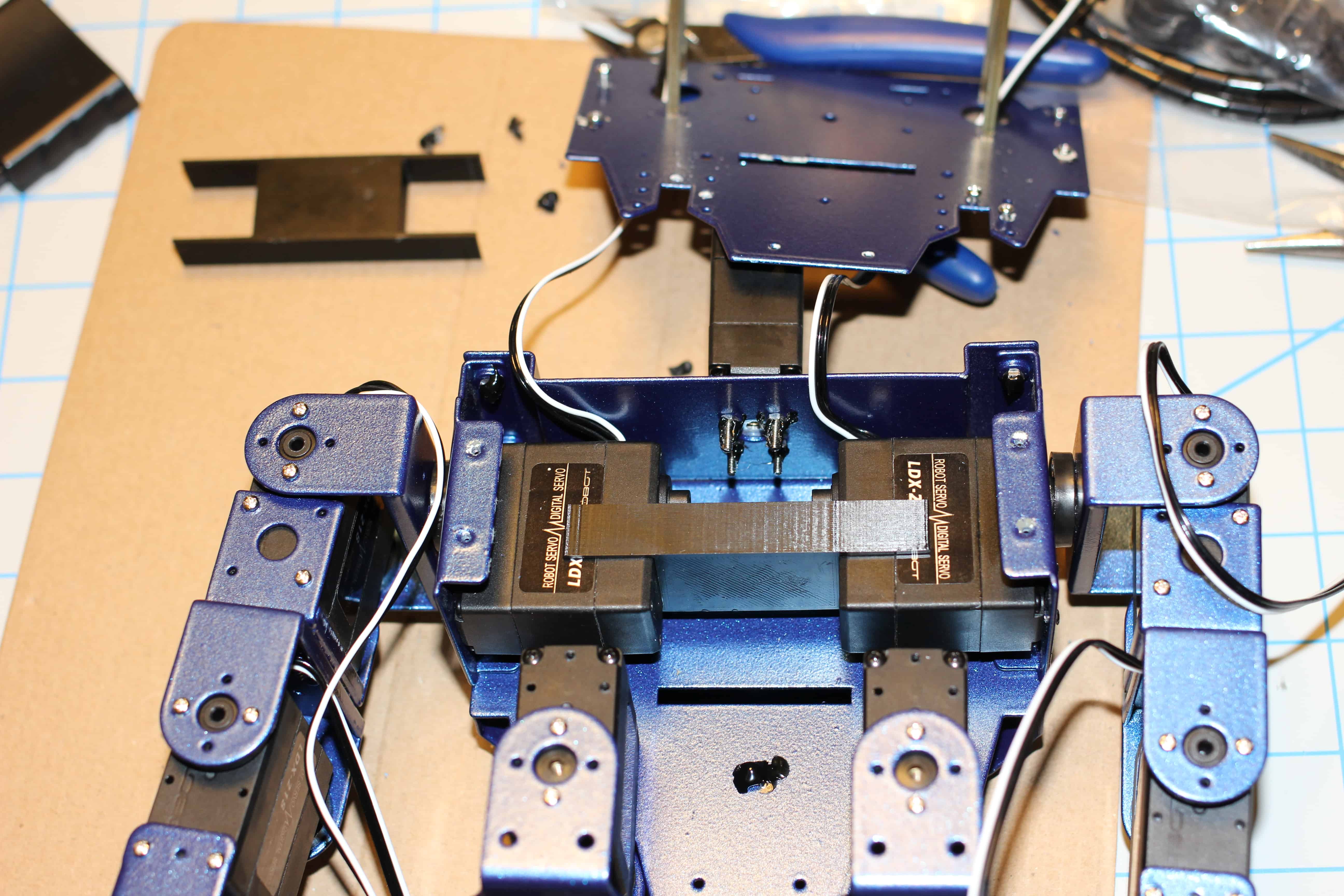
20. Notice the gap? The servos deform under load, we need to develop a brace.
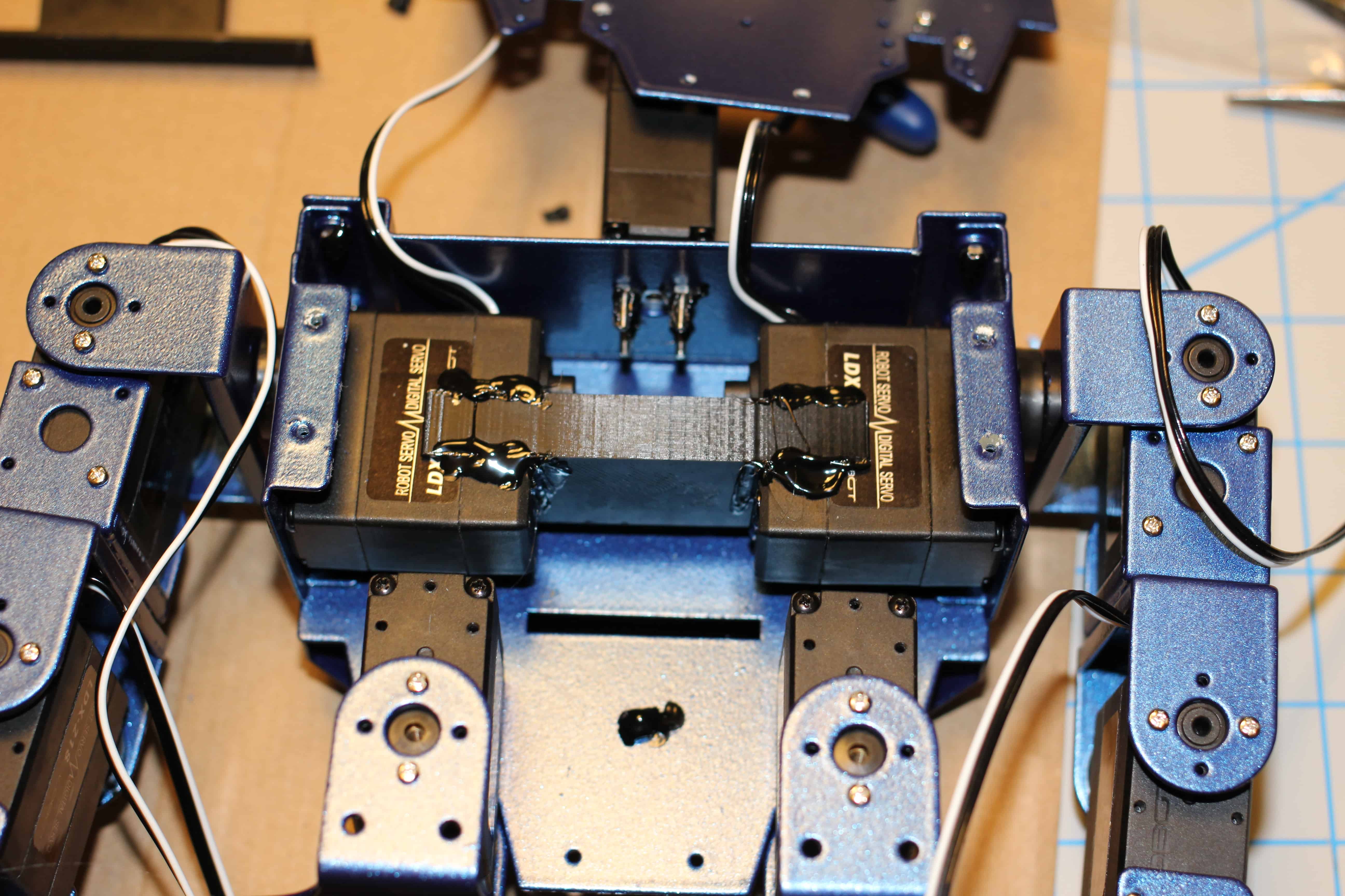
21. Much better.
22. Hot glue to secure in-place.
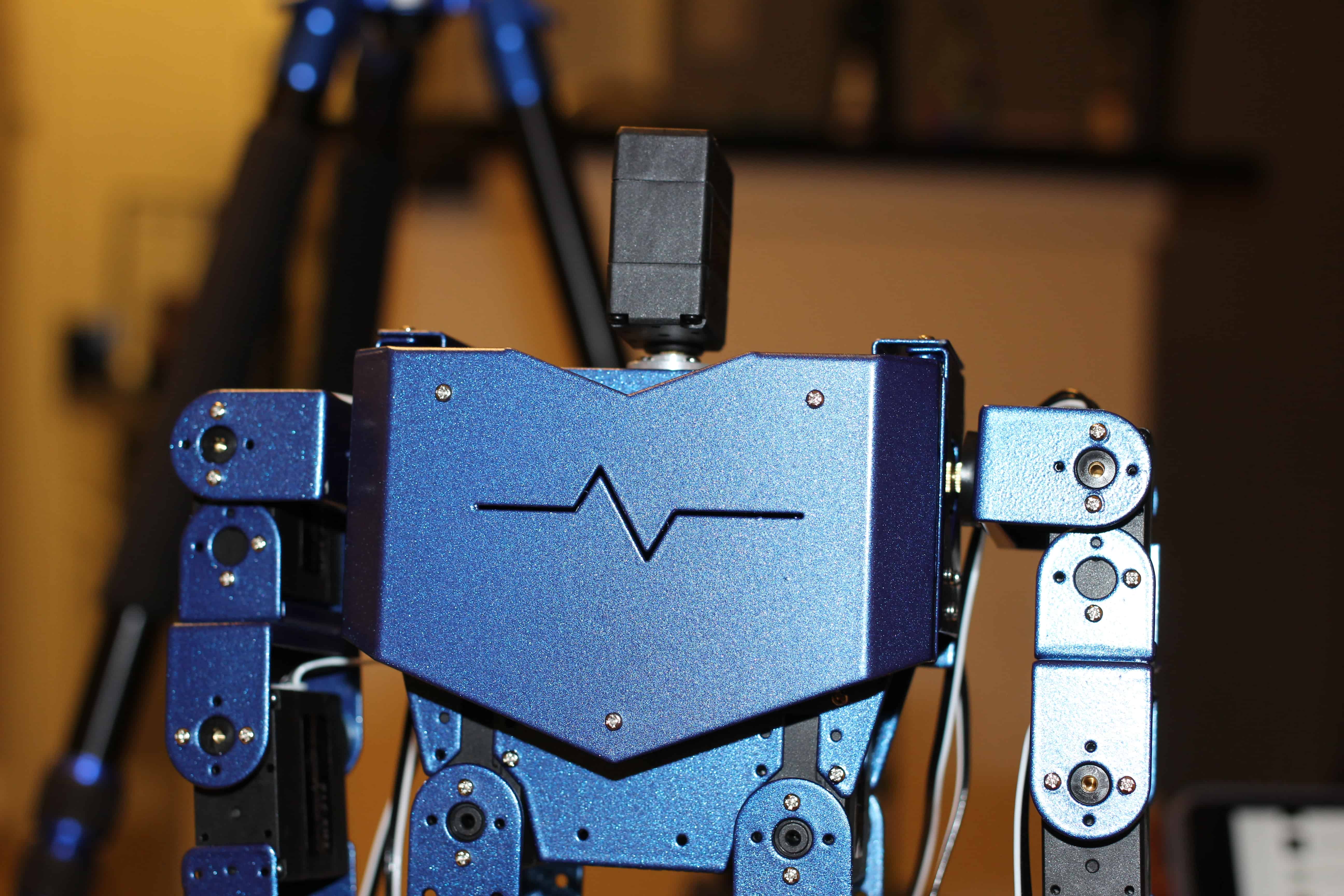
23. Now attach the front. Torso section done for now. Attach head.
24. Add servos to hips.
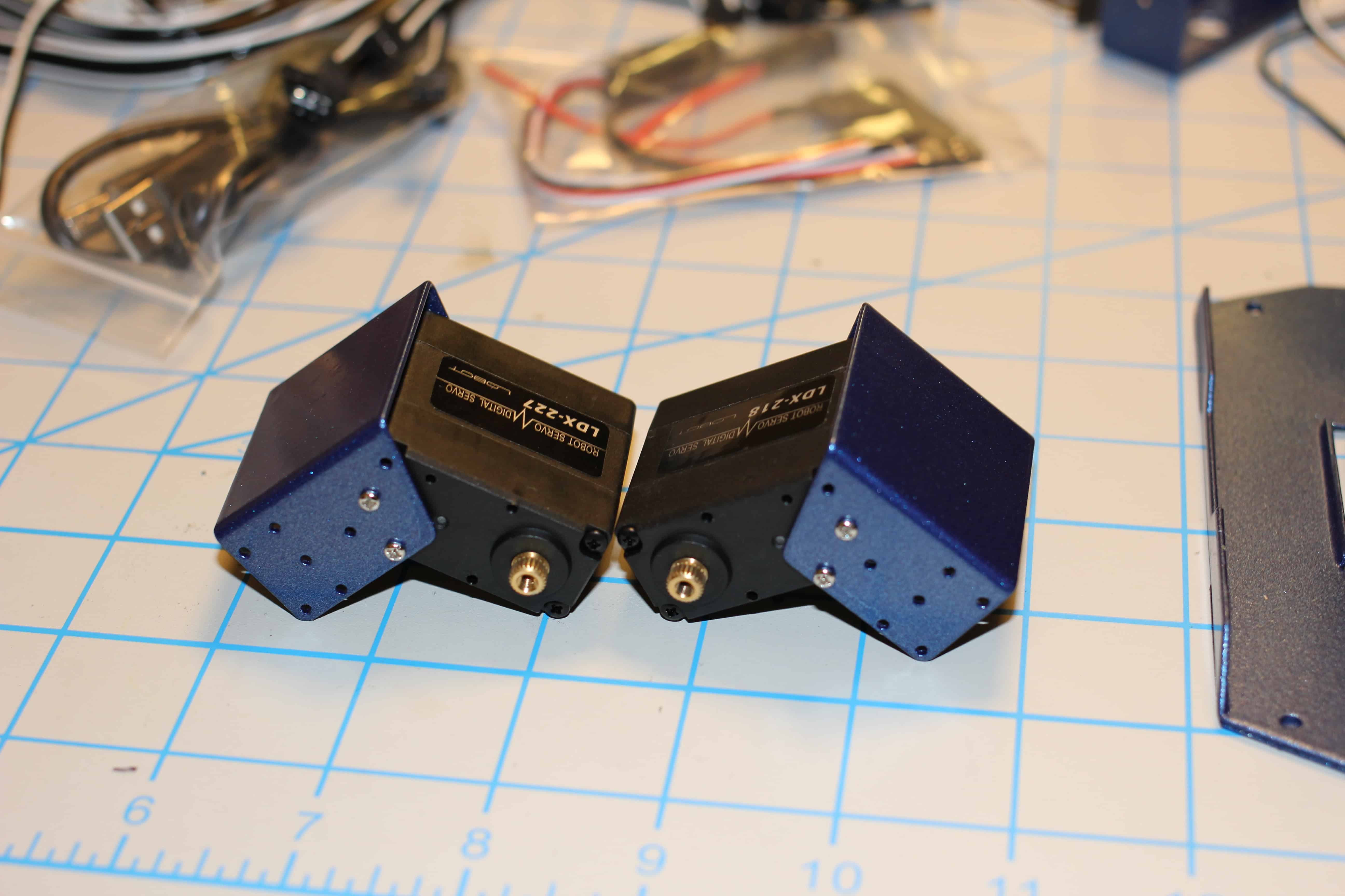
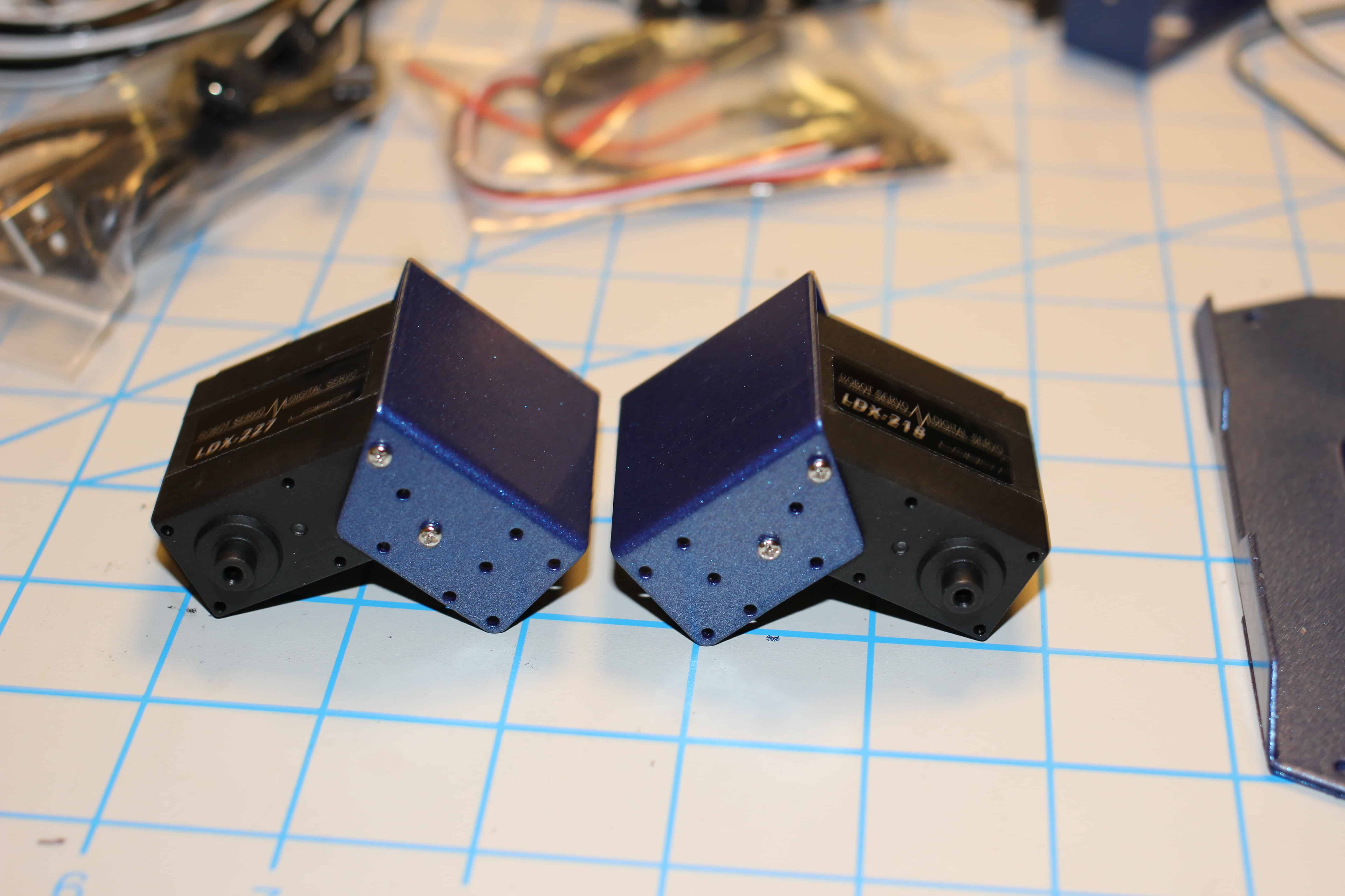
25. Time to build the arms, lineup a tooth disc like so.
26. Servos should be orientated accordingly.
27. Completed shoulder assembly.
28. Attach servos to bicep/forearm section.
29. Attach hands. Yay, arms are done. Set aside for the time being.
30. Mate legs with torso assembly.
31. Attach arm assemblies to shoulder servos.
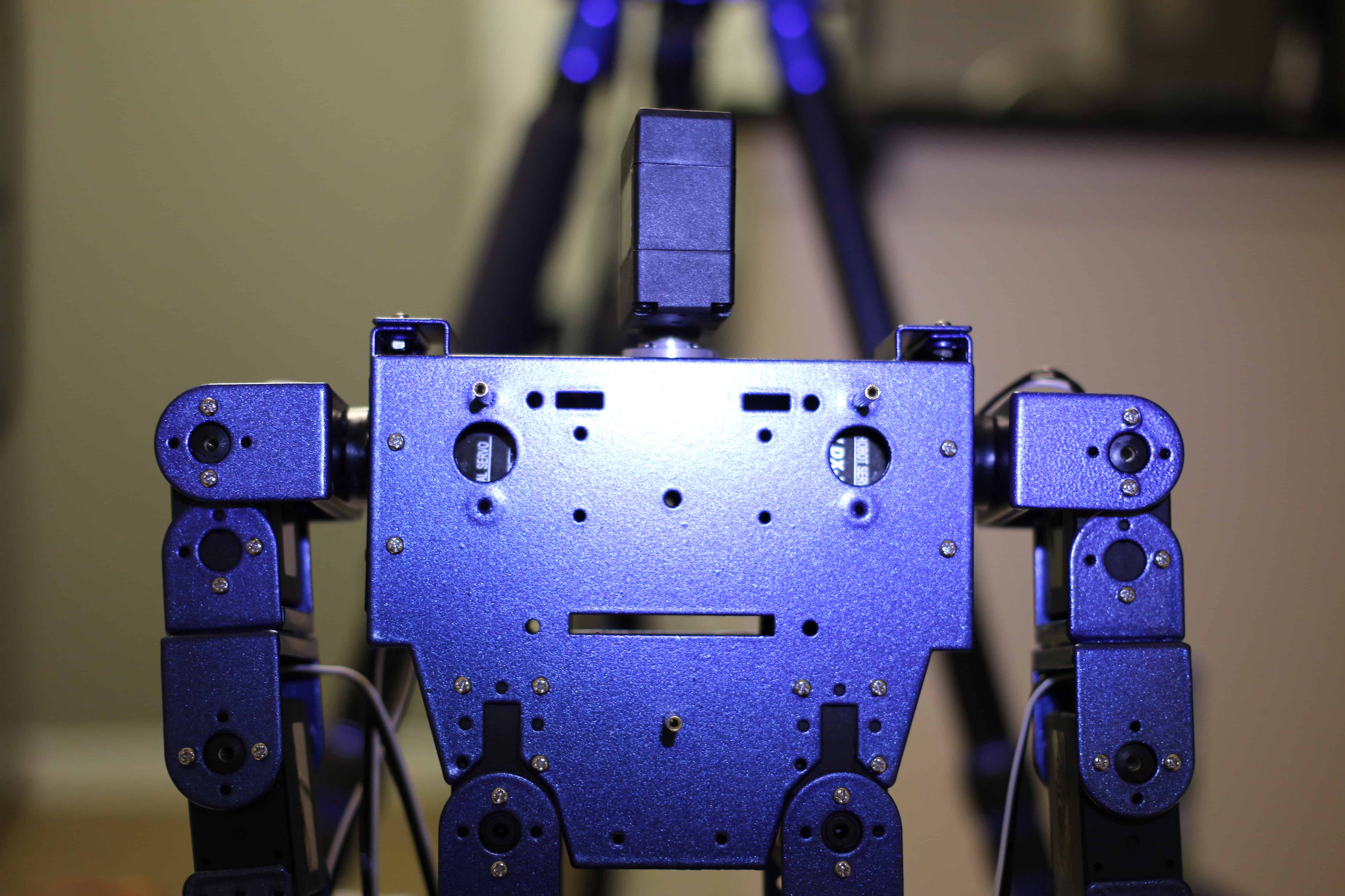
32. Attach chest-plate.
33. Route cables to the back of robot.
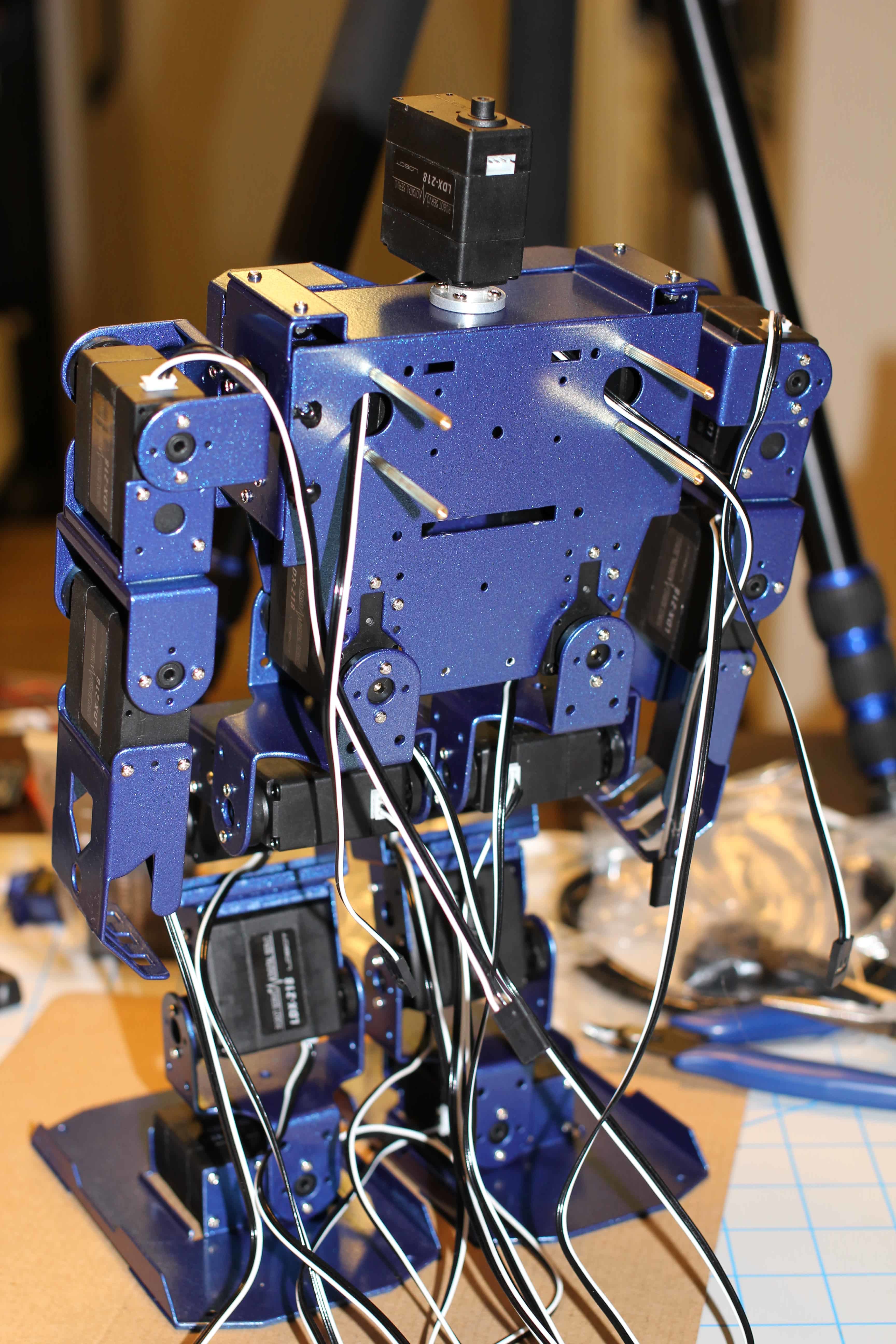
34. Time to label the cables. This will save a lot of time when we need to debug in the future. Here is the layout.
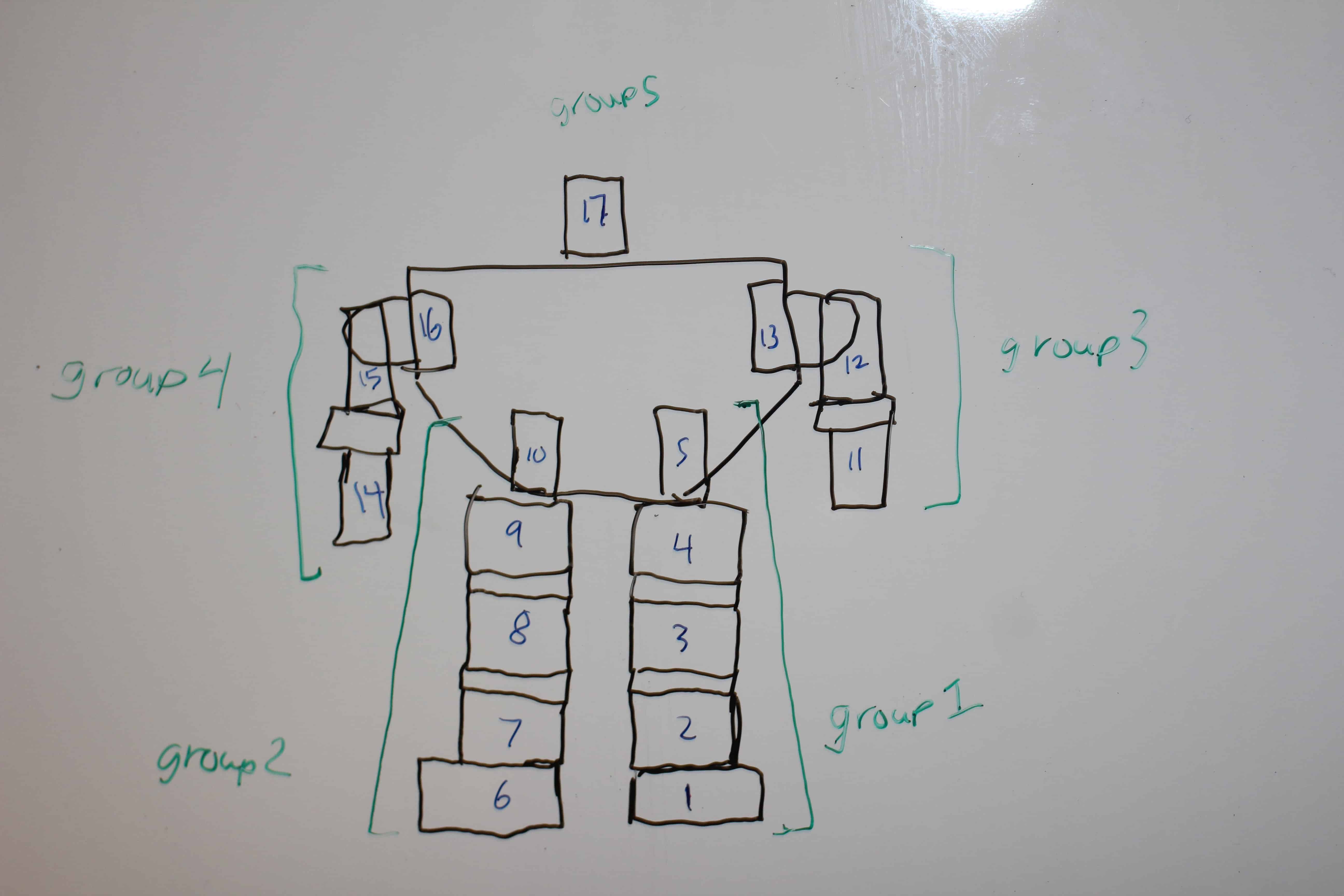
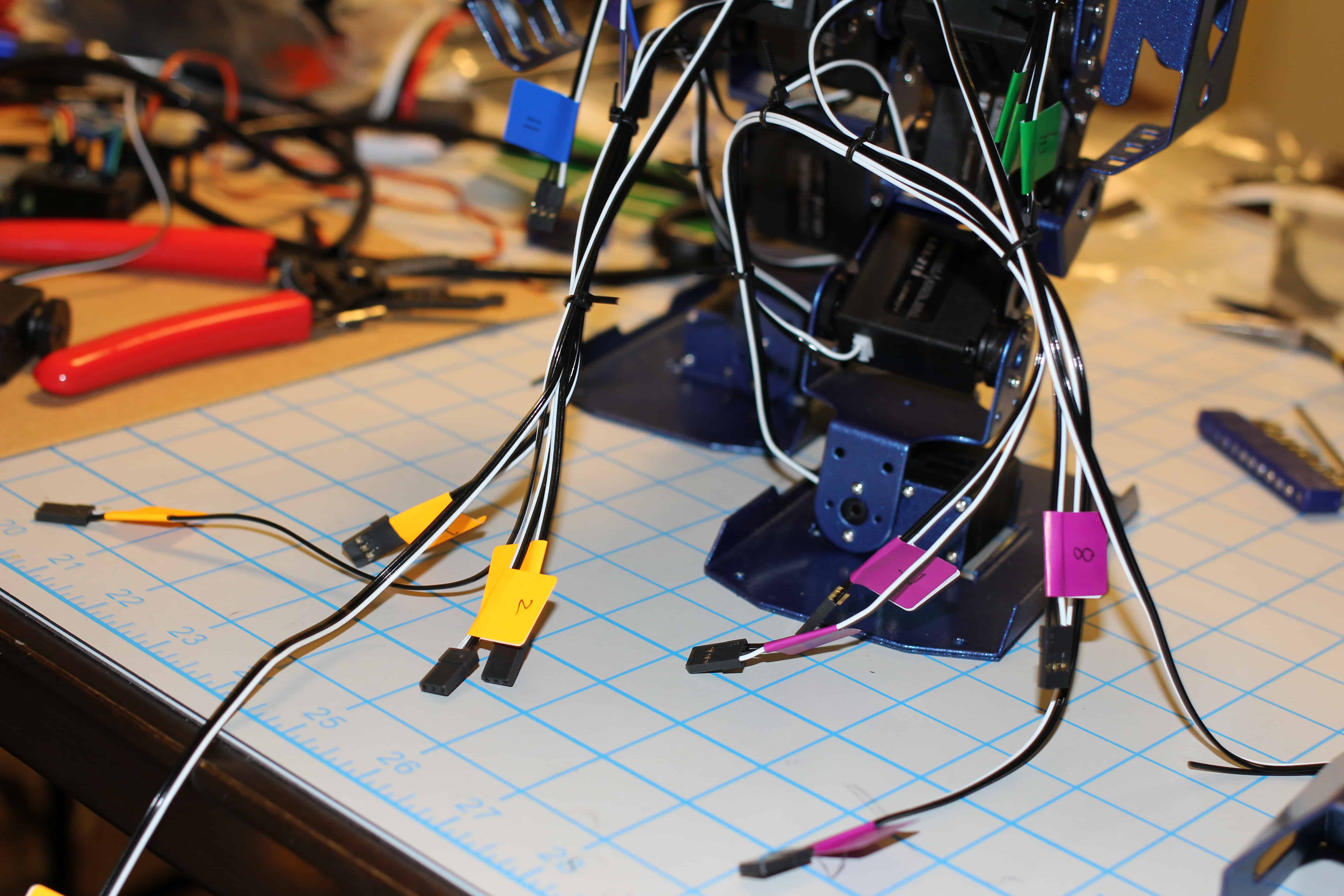
35. Cables labeled.
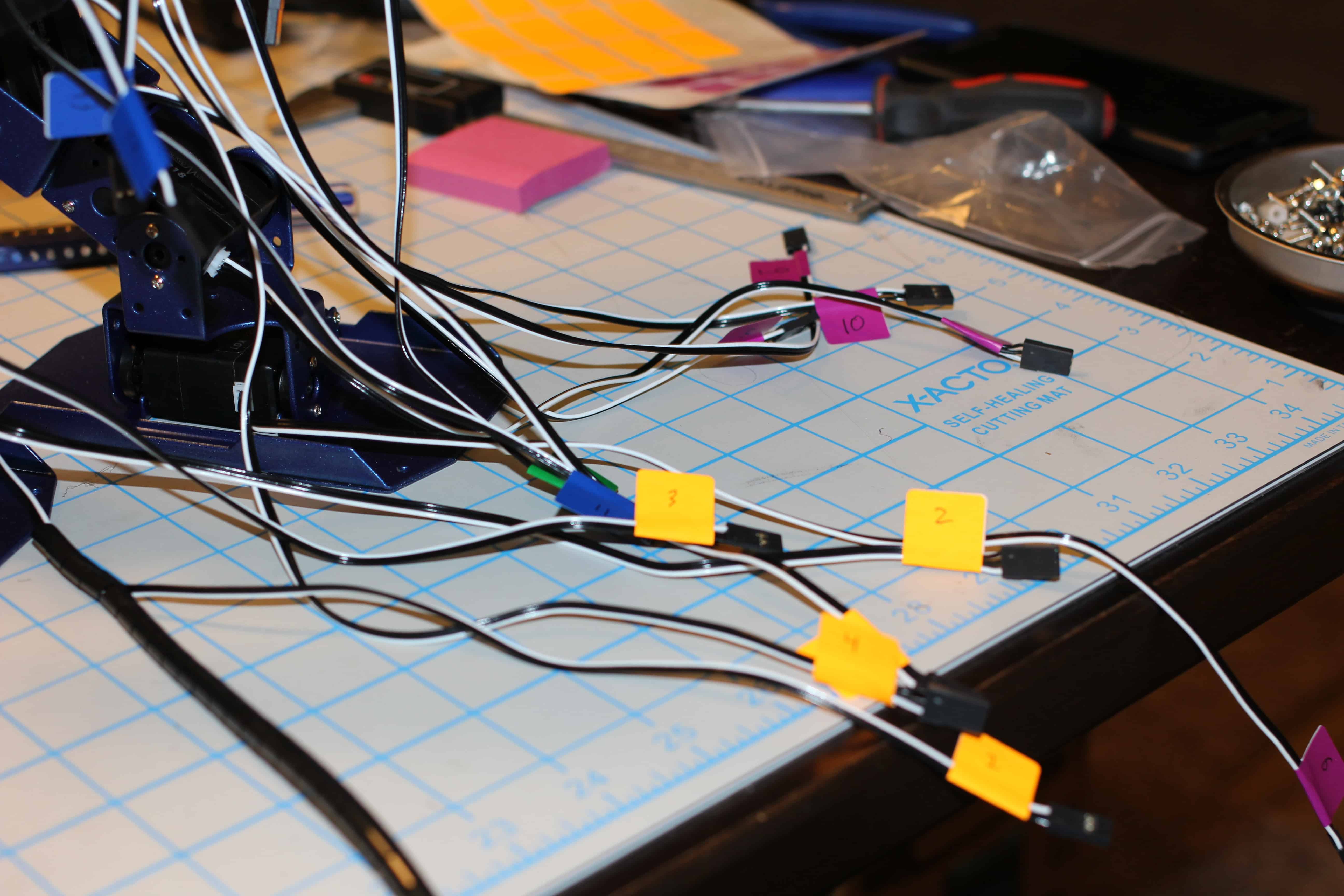
36. Loosely zip-tie the groups together for some minor cable management. Make sure there is enough slack for the limbs to move.
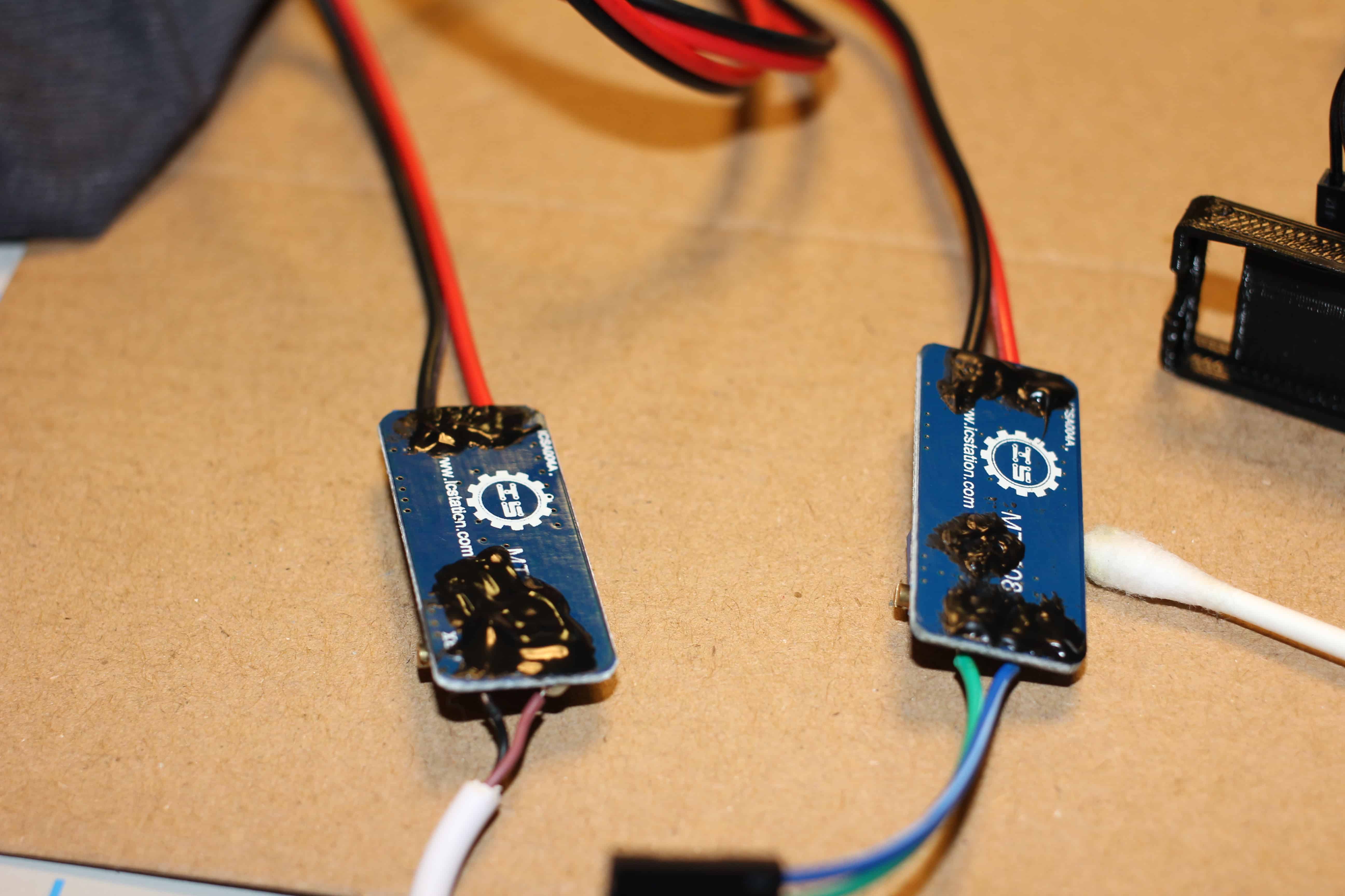
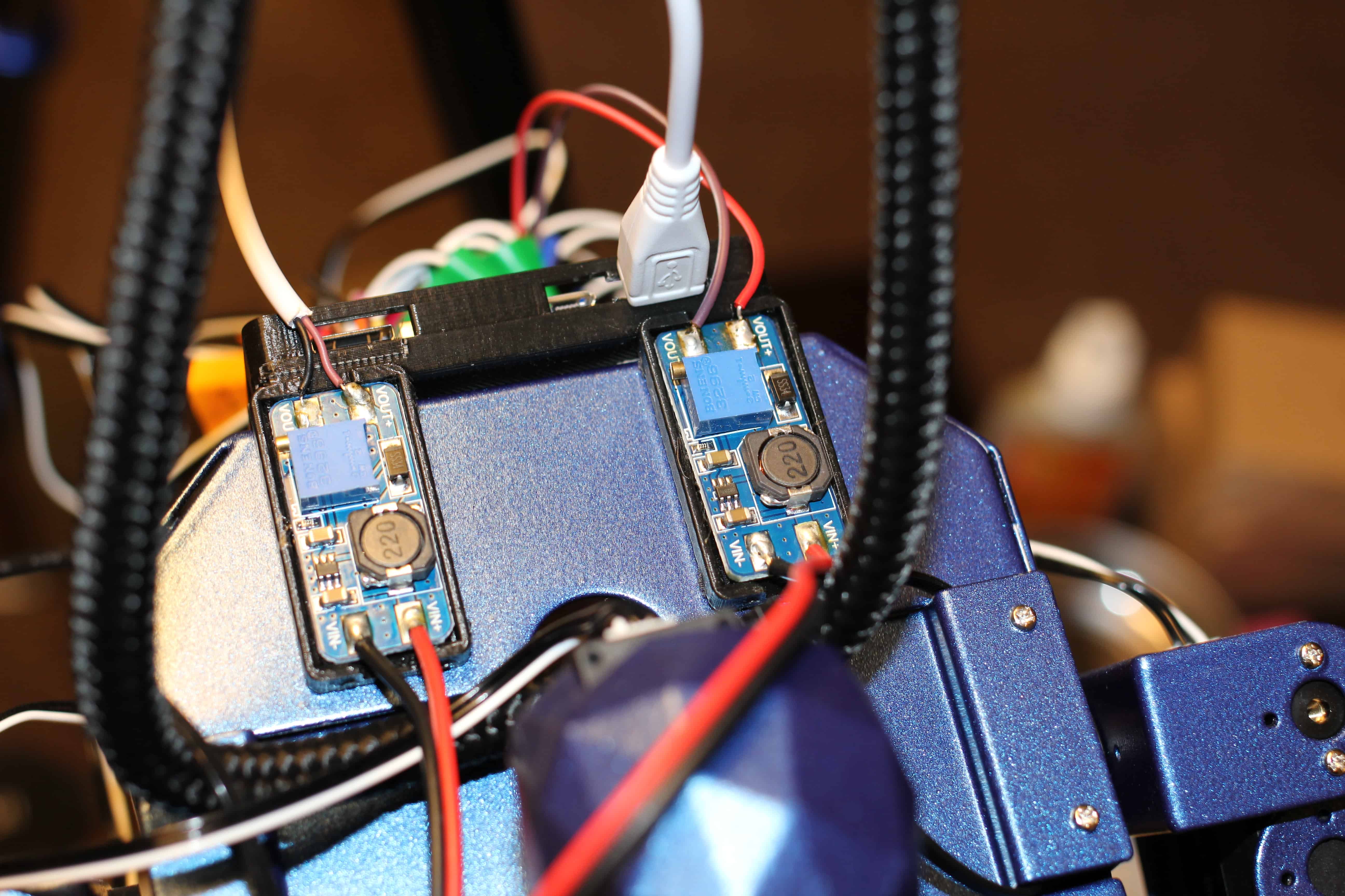
37. DC-DC boost module prep (note the DC-DC boost module on the right is note adequate to run the supplied servos). Use rubbing alcohol to clean bottom contacts.
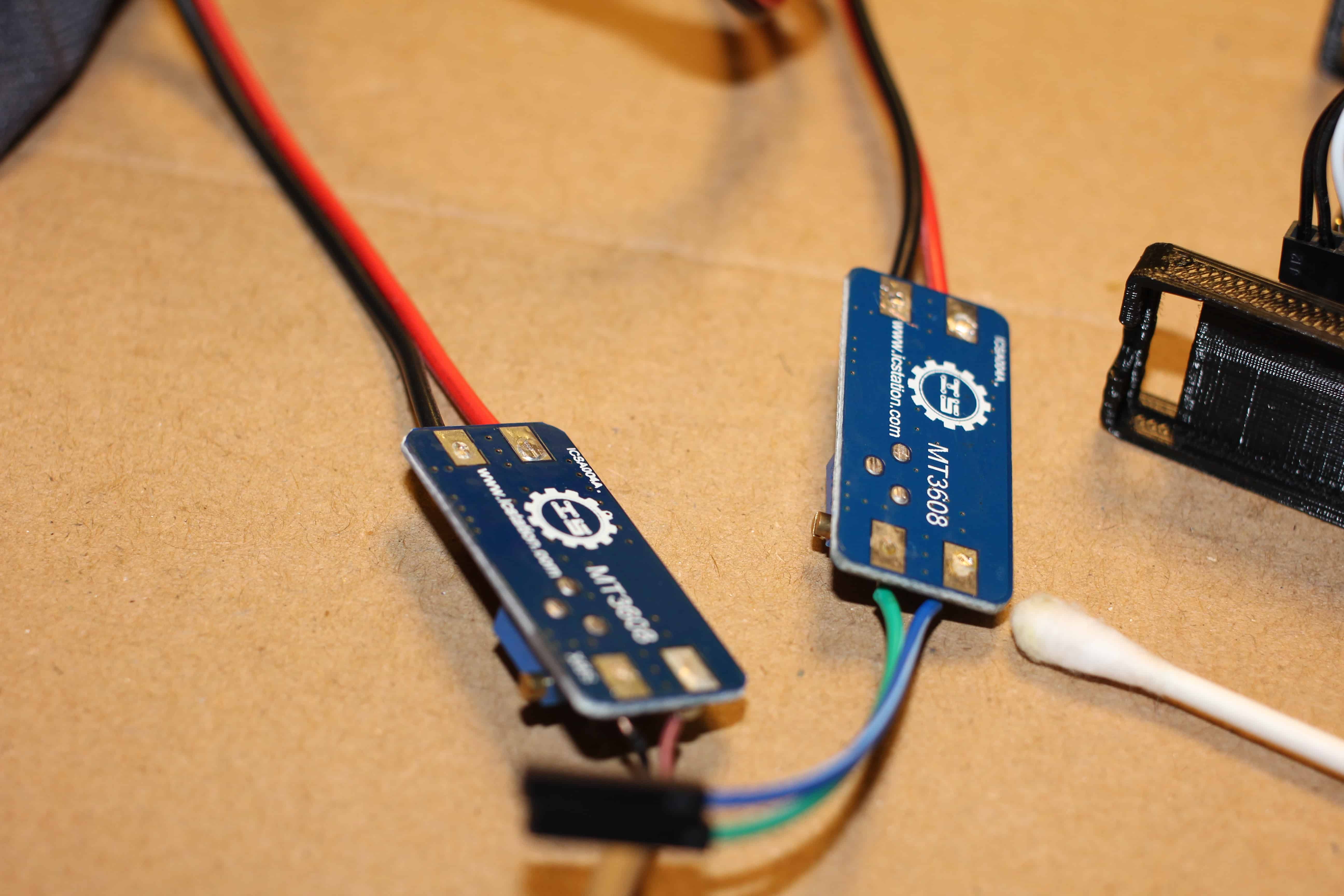
38. Insulate with liquid electrical tape. Great stuff, but smells terrible. Make sure you have adequate ventilation.
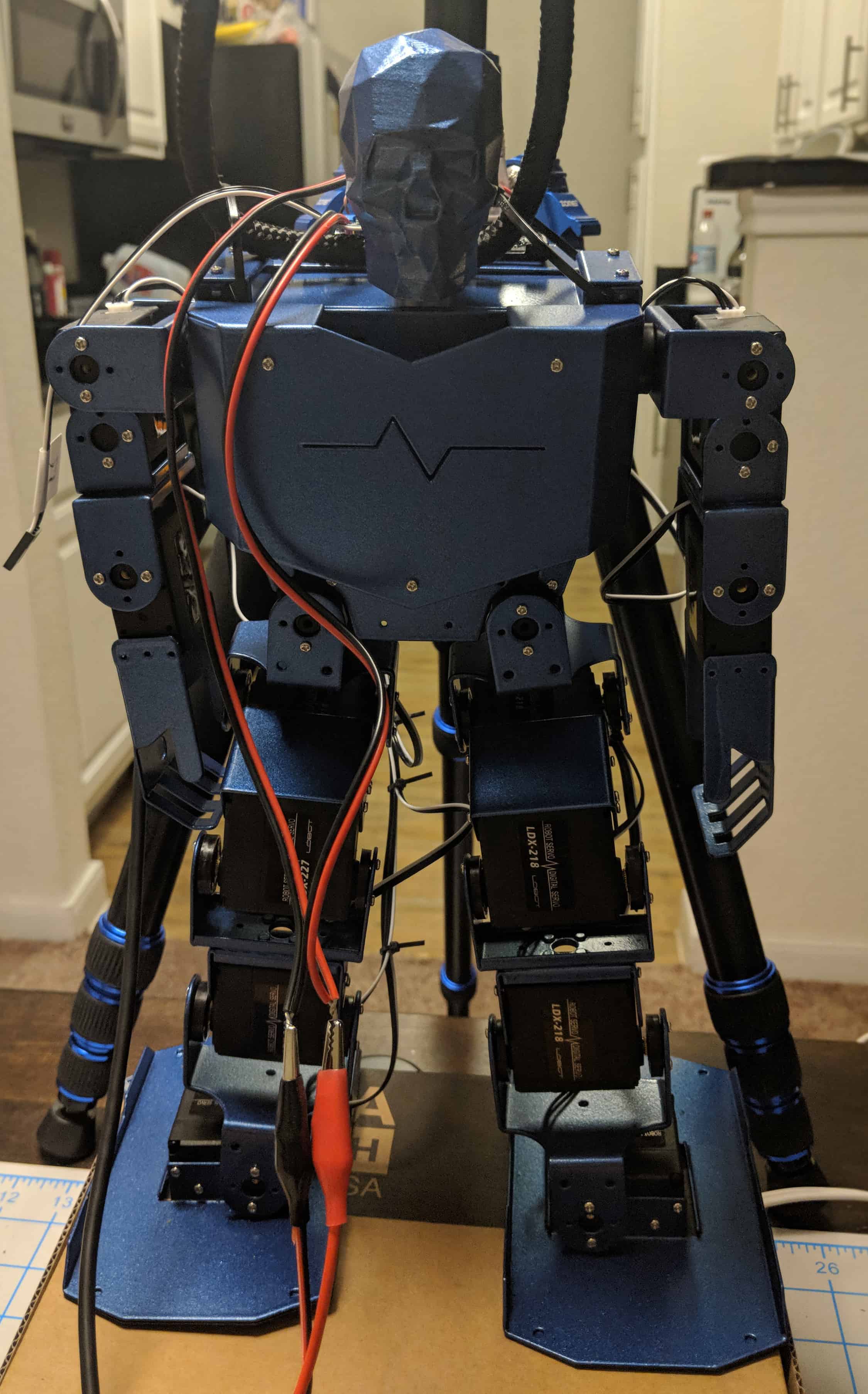
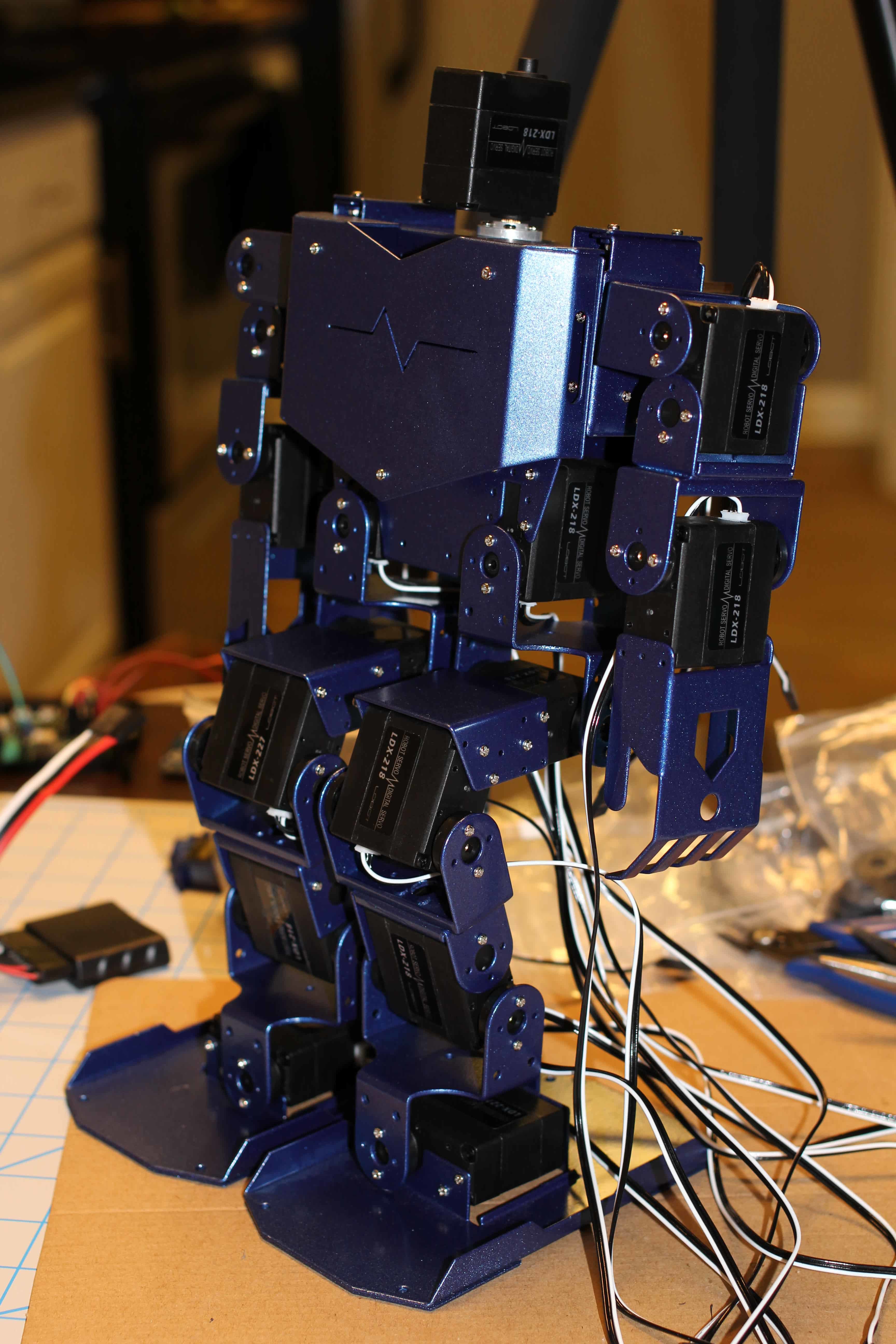
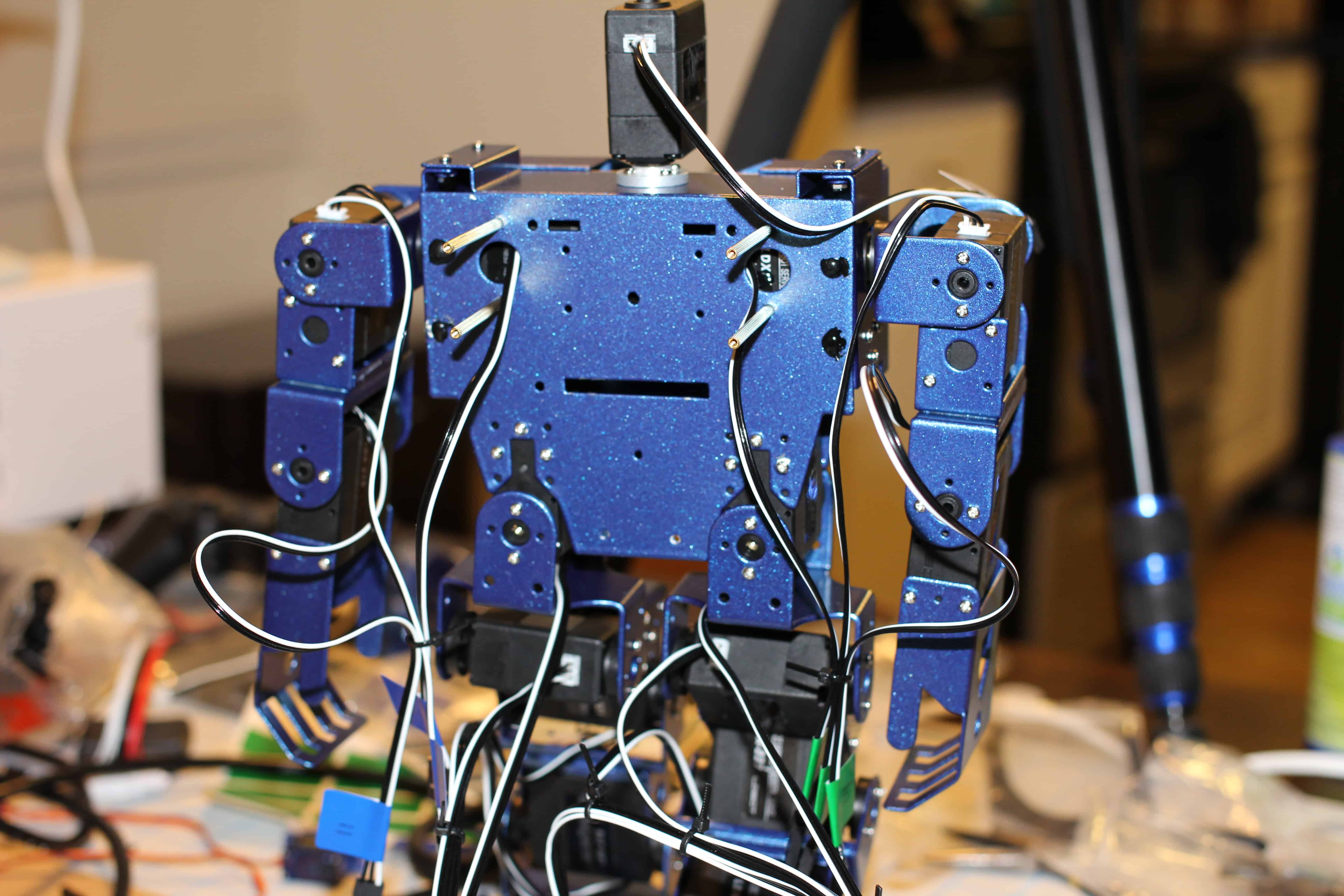
39. Fully assembled robot!!!
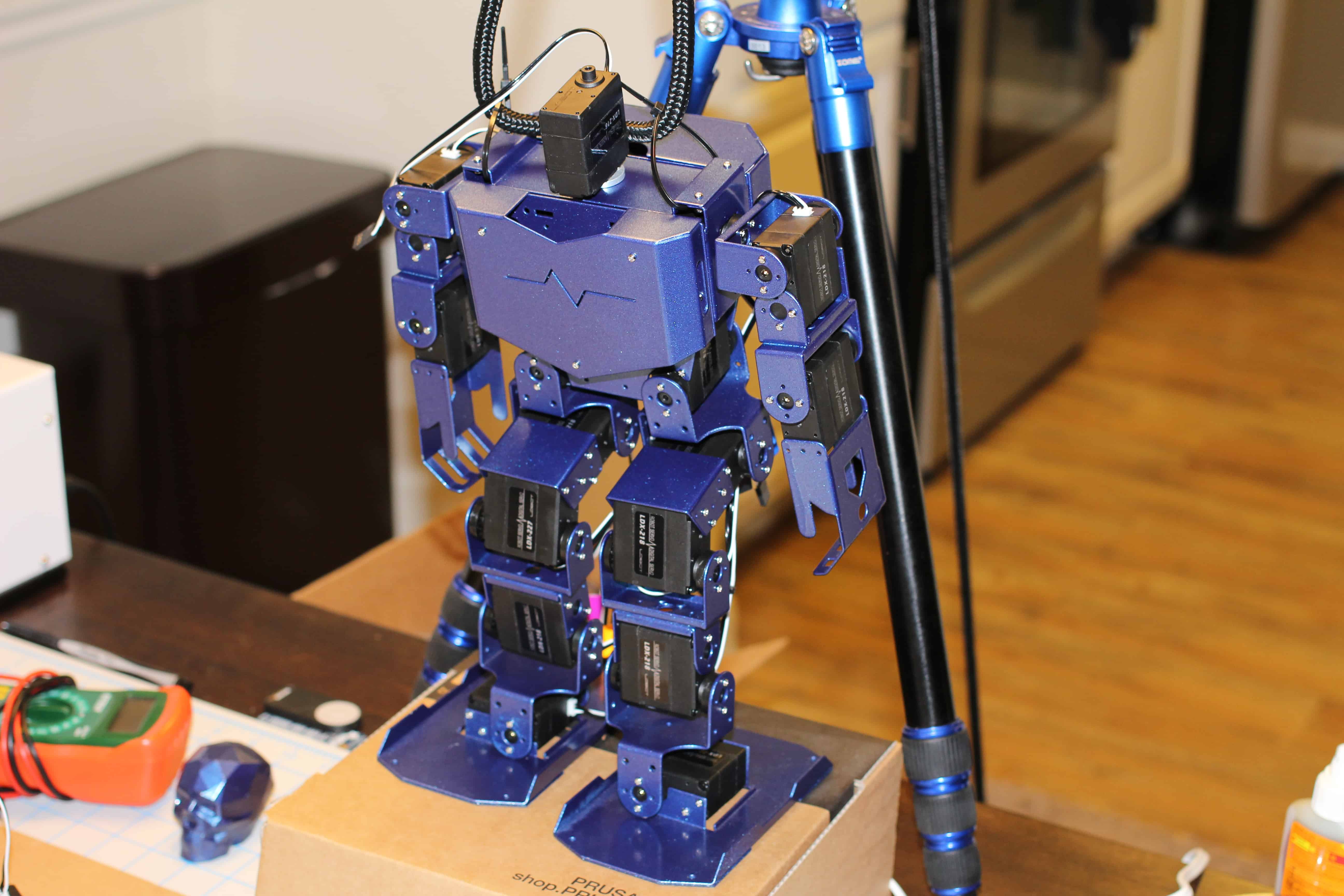
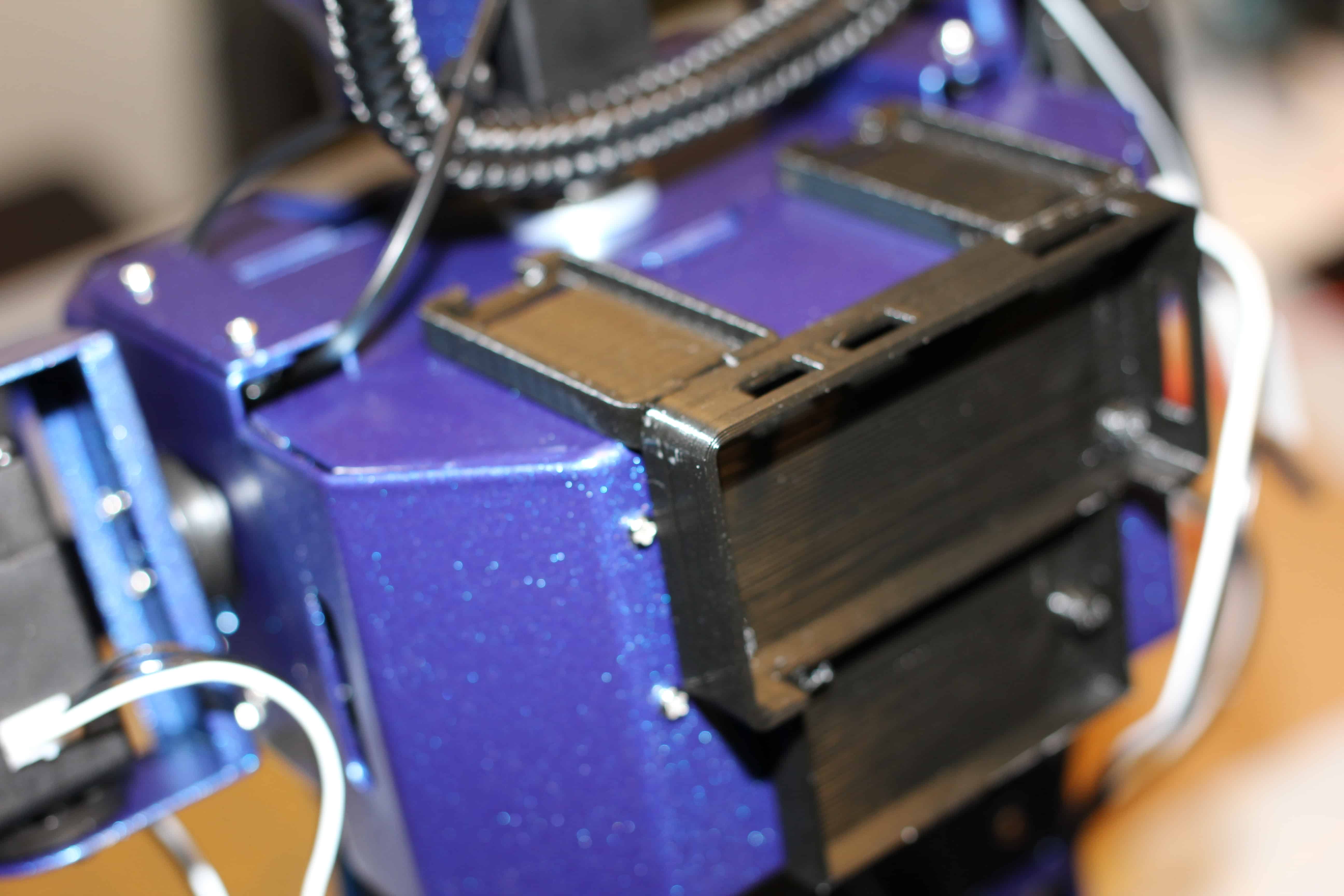
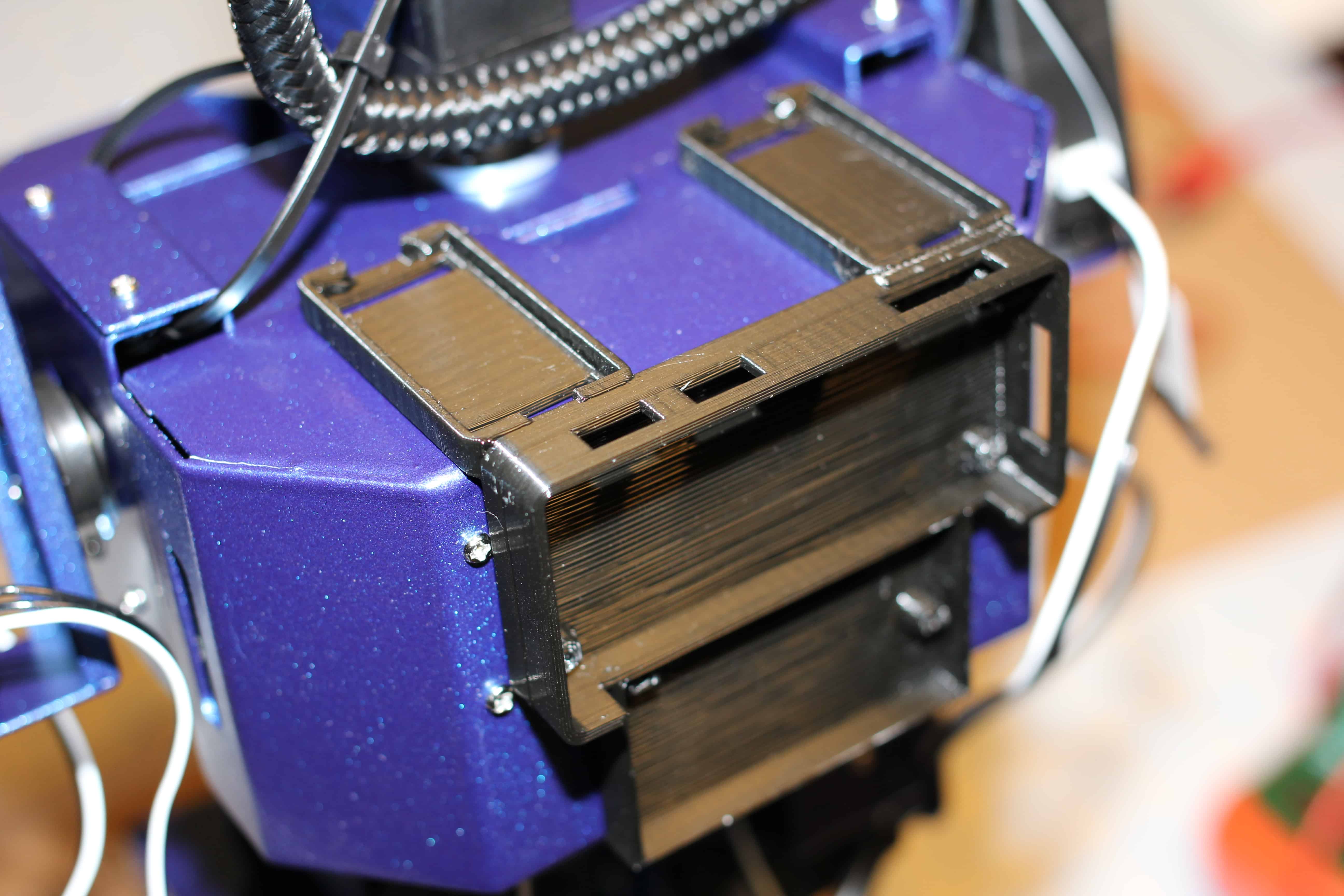
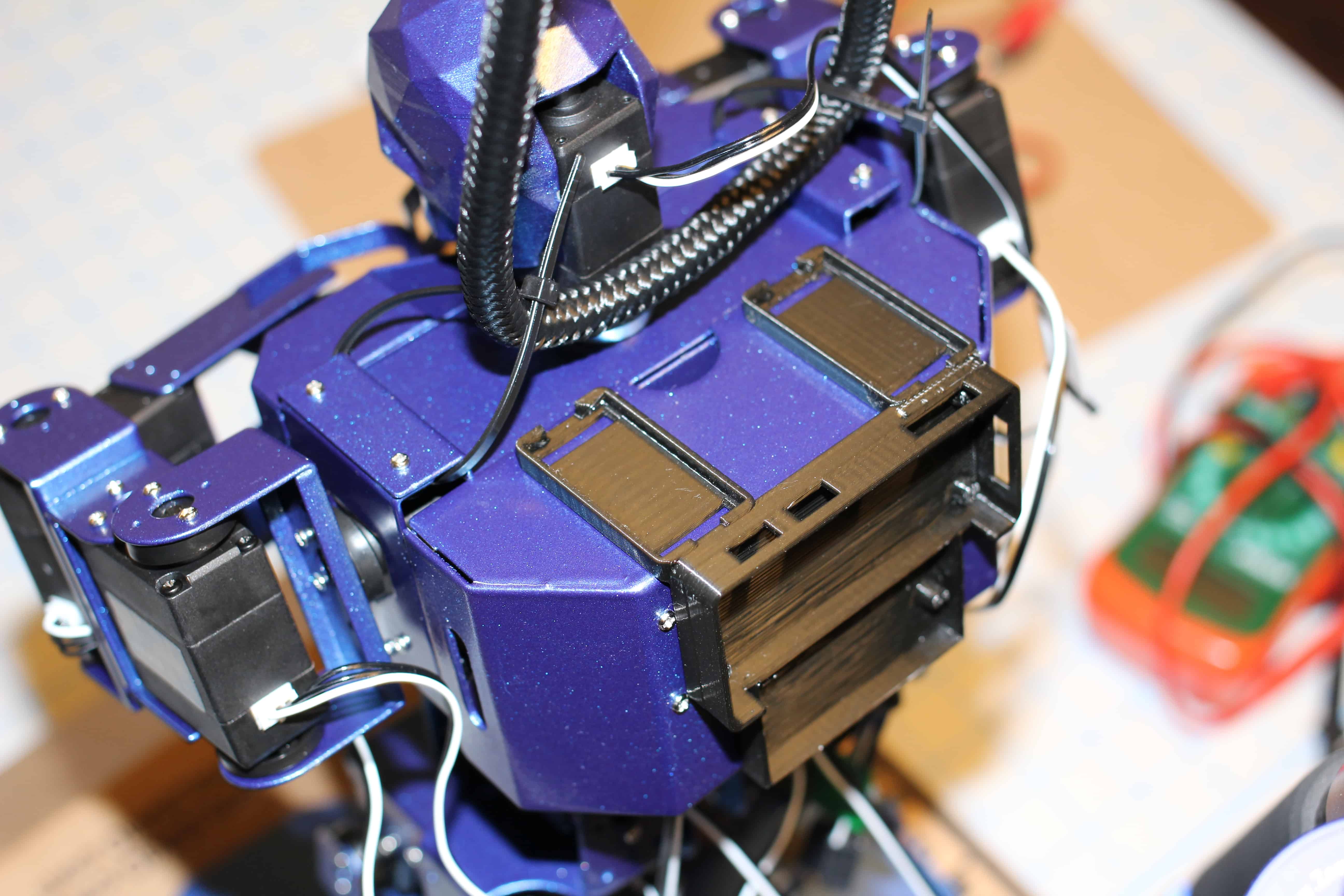
40. Adding the RPI zero/maestro controller backpack mount. Also, notice how the robot is hoisted by the shoulders. This should allow an easier time to program the movements of the robot, without it constantly falling over.
41. Wiring everything up.
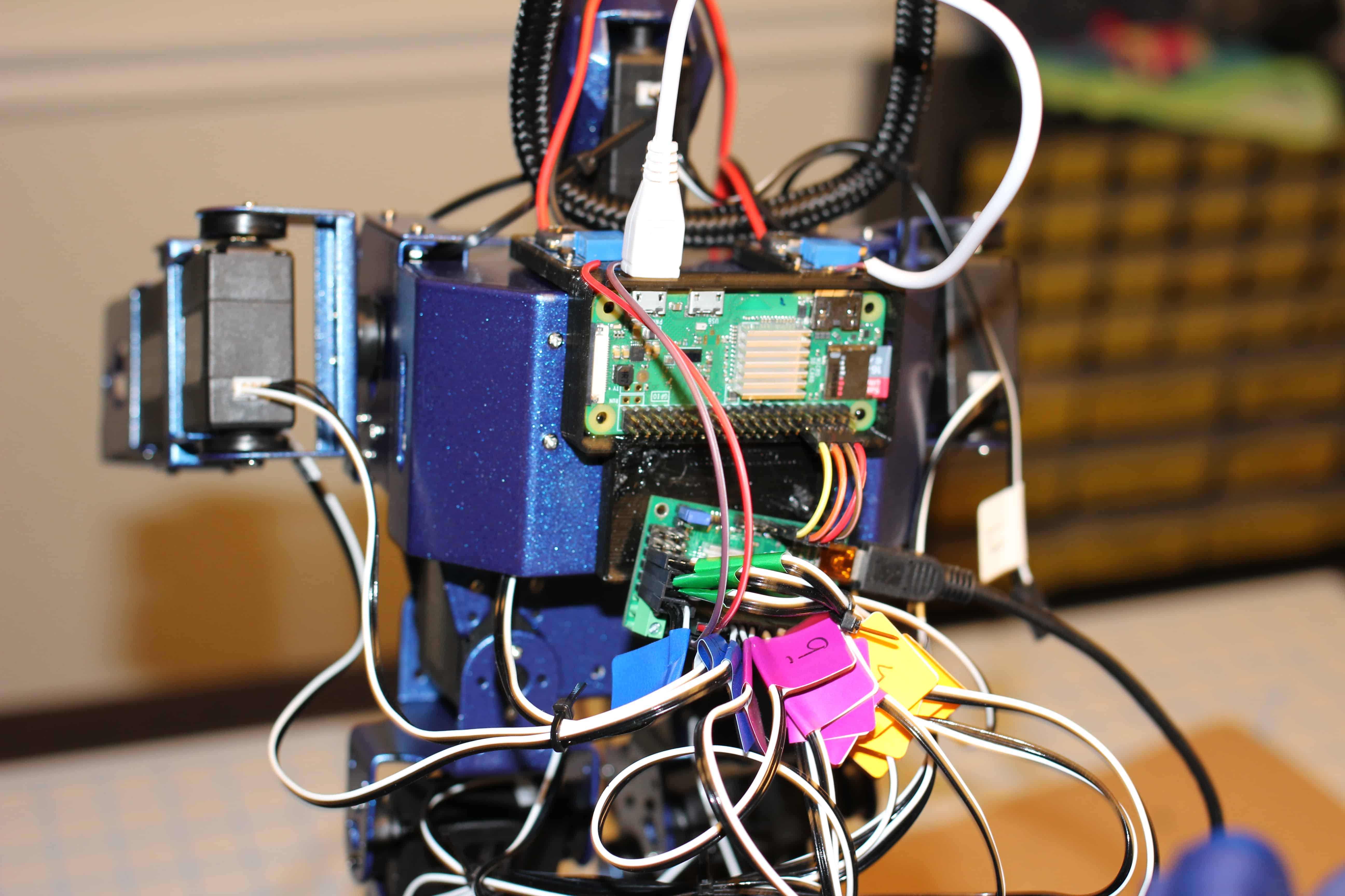
42. This section needs to be modified. The DC-DC boost module on the right cannot supply enough peak-Amperage and will eventually over-heat. However, it is connected to the Masestro controller and setup to supply 7.4 volts. The DC-DC boost module on the left supplies 5 volts to the raspberry pi zero. Currently, I have my bench power supply supplying 7.4 volts to the Maestro controller and a separate 5 volt power supply hooked up to the pi for testing purposes. Ideally both inputs of the DC-DC boost modules would be hooked up to a lipo battery pack to run the system untethered (I’ll update the tutorial once I finalize the power distribution/backpack mount).
REFERENCE LINKS:
Maestro Servo Controller Tutorial – https://www.piddlerintheroot.com/maestro-servo-controller/
CODE: